Model-Based Design for DO-178B
By Bill Potter, MathWorks
Software systems deployed in safety-critical applications in aerospace and other industries must satisfy rigorous development and verification standards. One of the most widely used of these standards is DO-178B, “Software Considerations in Airborne Systems and Equipment Certification.” DO-178B specifies 66 software development process objectives, distributed across various stages in the development lifecycle. It was published in 1992, when most software was hand-coded. As a result, it does not cover advanced software development technologies, and must be mapped onto the processes and tools in Model-Based Design.
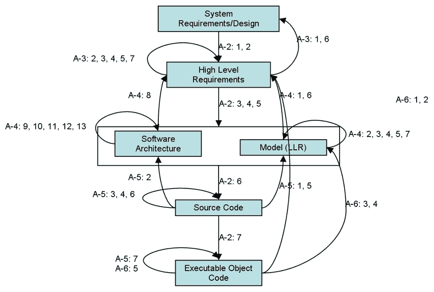
This article compares three approaches to using Simulink® system models and Model-Based Design to develop safety-critical systems that must satisfy the DO-178B standard:
- Using the model to capture only low-level software requirements
- Using the model to capture both high- and low-level software requirements
- Using separate models to capture the high-level and low-level software requirements
An autopilot design demonstrates a design flow that uses a single Simulink model as both the high-level and low-level software requirements.
Using the Models to Capture Both High- and Low-Level Software Requirements
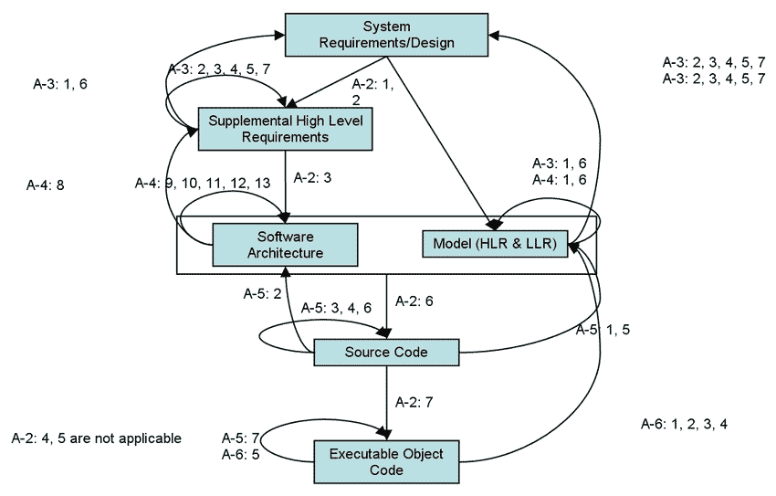
In the second approach, the Simulink model is considered to be both the high-level and low-level software requirements (Figure 2).
By reducing the number of artifacts that must be developed, this approach reduces the development and verification effort. To implement this approach, however, the system requirements must be sufficiently detailed to enable the models to be traced to and verified from those requirements.
Capturing High-Level and Low-Level Software Requirements in Separate Models
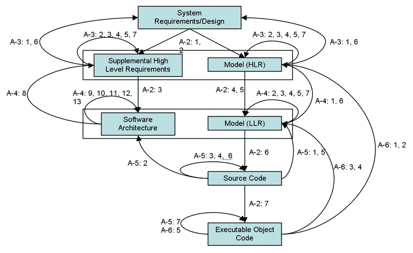
With this approach, a Simulink model captures the high-level software requirements. Detail is added to the model to capture the low-level requirements and for code generation (Figure 3). The high-level requirements model might be continuous-time, while the low-level requirements models used for code generation might be discrete-time.
The disadvantage of this approach is that two models must be maintained and verified, increasing the risk of error. The transition from the high-level requirements model to the low-level requirements model is another potential error point.
An Autopilot Example
This example uses a single Simulink model as both the high-level and low-level software requirements.
An autopilot is typical of the kinds of aircraft system that might be designed using Simulink and Model-Based Design. In a typical workflow, the control systems engineer performs trade studies and analysis for the autopilot and then provides the design to the software group to implement in a target system.
Because an autopilot controls the aircraft, it usually must meet the highest level of safety. As a result, it is challenging for the development team to conduct the necessary development and verification activities and to provide evidence to the certification authorities that those activities were carried out properly and completely.
The Design Workflow
The design workflow begins with the following steps:
- Capturing and verifying system requirements
- Designing the system
- Verifying the system design
- Allocating the system design to software
The design team then completes the software steps required by DO-178B:
- Defining and verifying software requirements
- Defining the software design and architecture
- Verifying the software design and the source code
- Generating and verifying executable object code
Capturing and Verifying System Requirements
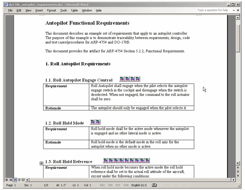
The system requirements for the autopilot's roll axis are provided in a Microsoft Word document (Figure 4). The team implements each requirement in a section of the document that also contains the rationale for the requirement. Using Simulink® Verification and Validation™ software, they can trace requirements directly to the design model via hyperlinks.
Requirements validation, which demonstrates that the requirements are complete and correct, is typically performed by reviewing a checklist of requirements standards for the project.
Modeling and simulation can assist in the validation of the requirements. As the system design is developed, you can simulate the model to ensure that the requirements are complete and correct . Simulation can uncover undesirable system behavior that was not considered in the requirements. In some cases, it can demonstrate that the requirements are not verifiable.
Designing the System
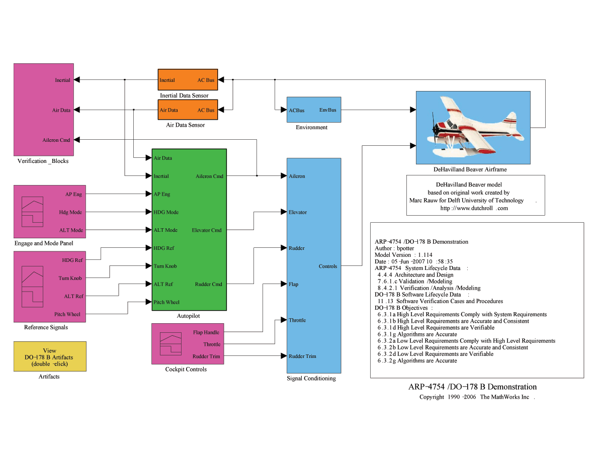
Figure 5 shows the system design model
The layout of the top level illustrates a basic system architecture that represents the system design and enables us to verify that the system design satisfies the system requirements.
Verifying the System Design
With the system design implemented in the Simulink model, we can verify the design against the system requirements without having to implement that design in actual hardware and software.
The top level of the model includes three signal builder blocks:
- Engage and Mode Panel
- Reference Signals
- Cockpit Controls
We can use these blocks to conduct specific tests during simulation.
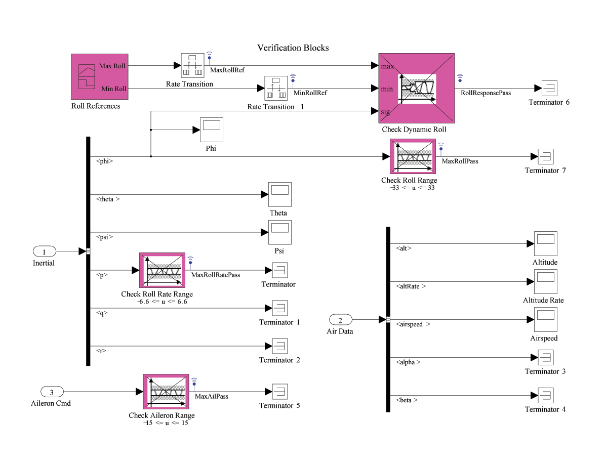
Of course, test stimulus alone is not enough to verify that the system design satisfies the requirements. We use Assertion blocks, contained in the subsystem Verification_Blocks (Figure 6), to determine whether the design satisfies the system requirements during simulation.
The Verification subsystem includes four Assertion blocks:
- Check Dynamic Roll
- Check Roll Range
- Check Roll Rate Range
- Check Aileron Range
The assertions Check Roll Range, Check Roll Rate Range, and Check Aileron Range provide minimum and maximum values for roll angle, roll rate and aileron angle respectively. These assertions are enabled during all test cases. The values, including tolerances, are based on the requirements document.
The assertion Check Dynamic Roll provides a window between minimum and maximum values that depends on the test case being executed. The signal builder block Roll References is used to provide the minimum and maximum values for each test case using signal groups.
Because we are using three signal builder blocks for test stimulation and one for assertion control requirements, we must coordinate the selected signal group for each of these blocks. With SystemTest™ software we can coordinate the test cases and automate test case execution.
SystemTest provides a framework for setting up tests in three phases: Pre Test, Main Test and Post Test.
Pre Test
We can use Pre Test to set up variables that are used during all iterations of Main Test.
During Pre Test, the following sequence is run:
Get requirements links, a MATLAB® element that gets requirements links from a signal builder block in the model
Set up descriptions, a MATLAB element that provides descriptions and pass/fail criteria text for each test which is included in the test report
Main Test
Main test enables us to iterate through test cases. In our example, we use the Test Vector parameter index to define the execution of the 20 test cases that we have defined.
During Main Test, the following sequence is run for each iteration:
Run Test Harness, a Simulink element that executes the model
Pre-Process Pass/Fail Data, a MATLAB element that computes the minimum value of each Assertion Block output logged during the execution of do178b_dhc2 in the Run Test Harness element
Verify Pass/Fail, a Limit Check element that checks the values from the Pre-Process Pass/Fail Data element in order to report the status of the assertions in SystemTest
Build Input Array, a MATLAB element that takes data logged from the inputs to the Roll_AP reference model in do178b_dhc2 model and prepares that data for used in the next Simulink element
Run roll_ap, a Simulink element that runs the roll_ap model
Pre-Process Comparison Data, a MATLAB element that computes the difference between the model reference output of roll_ap generated during Run Test Harness and the output generated directly from the roll_ap model during Run roll_ap
Verify Results Match, a Limit Check element that verifies that the maximum difference between the results computed in Pre-Process Comparison Data
Save MAT File, a MATLAB element that saves data logged from the Simulink elements to a MAT file for use in generating a test report during Post Test
Save Excel File, a MATLAB element that saves the data logged for the reference model roll_ap in Run Test Harness so that the data can be used to verify the executable object code target system
Post Test
We can use Post Test to analyze variables that are computed during all iterations of Main Test. During Post Test the following sequence is run:
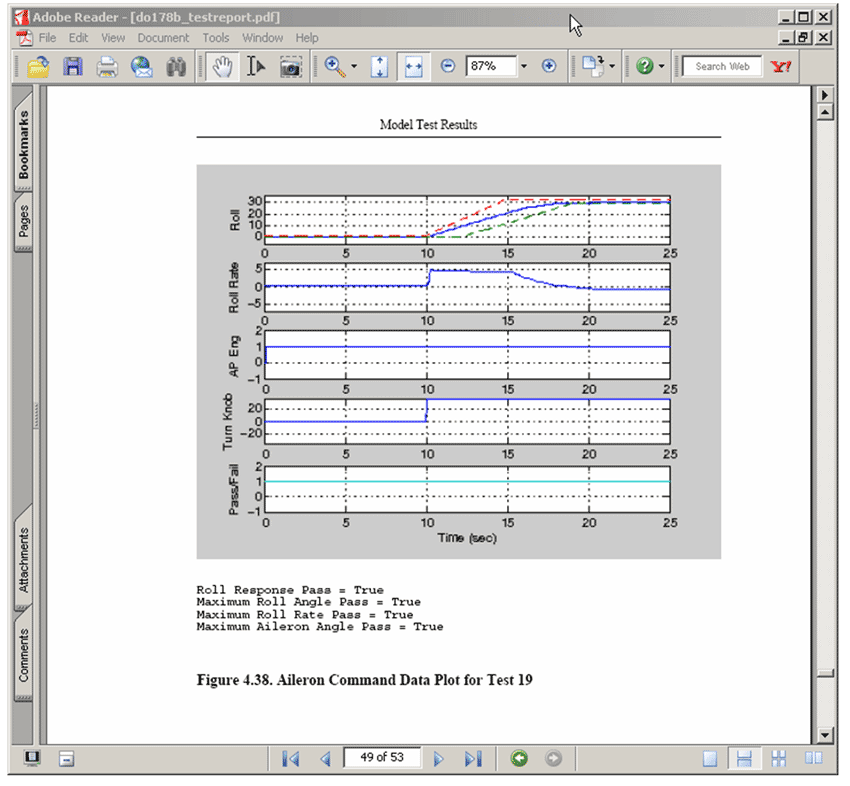
Generate Test Report, a MATLAB element that generates a test report in PDF format using the MAT file data that was stored during Main Test (Figure 7)
Run Model Advisor, a MATLAB element that runs a Model Advisor report for the model roll_ap
Generate Requirements Report, a MATLAB element that generates a requirements traceability report for the system requirements document and the roll_ap model
Generate Target Code, a MATLAB element that generates target code for the roll_ap model
Defining and Verifying Software Requirements
Specific functions from the system design are allocated to software to form the software requirements. In our example, the Autopilot subsystem (Figure 8) is allocated to software, and becomes the high-level software requirements.
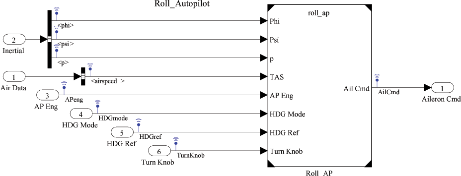
The Autopilot subsystem architecture is further broken down into three subsystems: Roll_Autopilot, Pitch_Autopilot, and Yaw_Damper. The Roll_Autopilot subsystem contains a Model Reference block, Roll_AP (Figure 9).
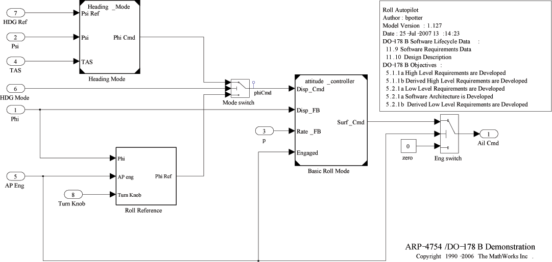
The Roll_AP function is contained in a separate model that is called from the system model (Figure 10). We can look inside the roll_ap model to see the functionality that is allocated to software.
The roll_ap model architecture is broken down into two reference models, Heading Mode and Roll Reference, and one subsystem, Basic Roll Mode.
For DO-178B, we must provide requirements verification artifacts demonstrating system requirements accuracy and consistency, verifiability, and algorithm accuracy. We can use the system design verification activities described in the previous section to partially meet these objectives. We must also review the model against the system requirements using a checklist or other measure.
We generated a requirements traceability report using the Simulink® Report Generator™ product during the Post Test phase of SystemTest.
As a part of the DO-178B lifecycle, we must verify that the high- and low-level requirements comply with DO-178B standards. We must also show that the requirements are compatible with the target computer. Simulink Model Advisor lets us perform static checks on the model to verify many standards automatically and to verify certain code generator option settings related to hardware compatibility.
Defining the Software Design and Architecture
The software design and architecture are defined within the roll_ap model and the Heading_Mode and attitude_controller reference models for the control portion of the roll autopilot function. For this function we generate the code directly from the high-level software requirements. As a result, the model satisfies both the high- and low-level software requirements.
Additional design and architecture activities will be required to fully define the high- and low-level software requirements. For example, there will be requirements and design associated with processing the inertial reference and air data sensor inputs, passing those inputs to the model inputs, and scheduling these tasks in the proper order.
Verifying the Software Design and the Source Code
Because we have combined the high- and low-level software requirements, we can use the software requirements verification activities previously described to cover software design verification.
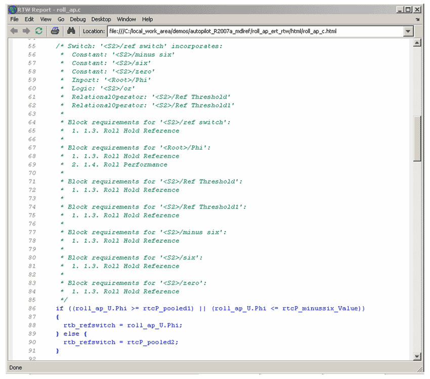
The source code is generated from the roll_ap model using Real-Time Workshop® Embedded Coder™. The code includes comments that trace each line of the code back to the model and to the requirements document (Figure 11).
Source code is usually verified using code reviews. We use Polyspace™ products to perform automated verification activities on the source code. These checks detect any MISRA C compliance issues, run-time errors, unreachable code, uninitialized variables, and data coupling issues.
We generate the executable object code from the source code using third-party compilers and links. We can generate make files for the software build process manually or by using Real-Time Workshop Embedded Coder.
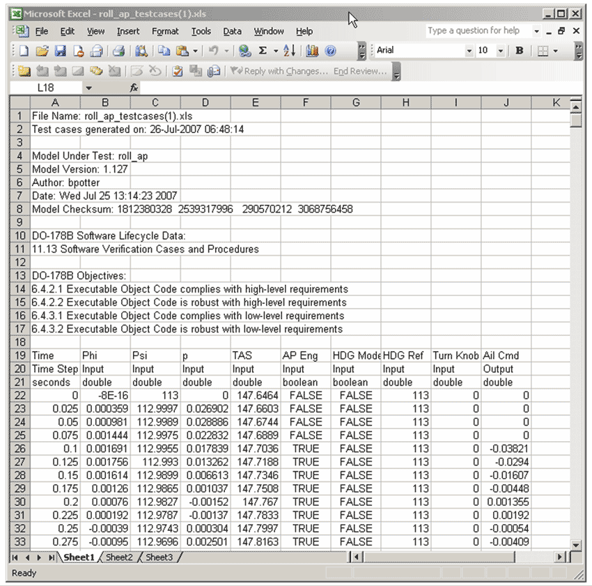
In the System Design Verification phase, we saved Excel® files during simulation for use in executable object code verification. The file shown in Figure 12 is a typical example of how the data might be used by a software test platform to run tests on the executable object code. This file contains data representing the time and the input and output data for each time step.
During requirements-based testing, we must also perform structural coverage analysis on the code to measure statement, decision and modified condition or decision coverage. This is one of the most expensive and time-consuming aspects of the DO-178B objectives.
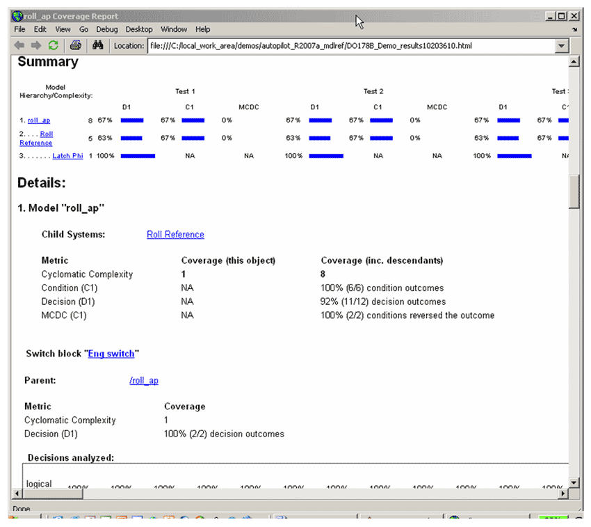
During the simulations run from SystemTest, a Model Coverage Report was generated automatically, thus providing a measurement of the effectiveness of the requirements based tests early in the development process rather than after code is tested (Figure 13).
The Model Coverage Tool can provide the following information:
- Cyclomatic complexity
- Decision coverage
- Condition coverage
- Modified condition/decision coverage
- Lookup table coverage
- Signal range coverage
Published 2008
