Developing Control Systems for Next-Generation Rescue Stairs with Model-Based Design
By Clemens Friedl, Rosenbauer Group
When an incident occurs on board an aircraft or around a runway, first responders need quick access to the cabin. In such cases, quickly deploying rescue stairs can facilitate a speedy evacuation or enable medics to provide timely medical assistance to passengers or crew members.
At Rosenbauer, we recently redesigned our Aircraft Interior Access Vehicle—better known as rescue stairs—to minimize setup times while maintaining high safety standards and improving ease of use (Figure 1). As we began this effort, we also took the opportunity to remake our existing control software development process, which had been based on handwritten coding and extensive on-vehicle testing. We replaced this outdated approach with one that we previously thought was economically feasible only for much larger OEMs. Specifically, we used Model-Based Design with MATLAB® and Simulink® to verify our early control designs via simulation, enable internal and external development teams to run hardware-in-the-loop tests, generate production code, and cut development time on the project in half.

Figure 1. Rosenbauer rescue stairs.
Control Design Opportunities and Challenges
When we designed the control system for our previous generation of rescue stairs, the control hardware available at the time was more limited. As a result, we needed to distribute our control software across six ECUs. We also needed significant redundancy in cabling and other components to meet safety requirements.
For the current design, new hardware made it possible for us to simplify the architecture significantly and use just two ECUs. One safety-certified ECU handles all safety features, with software developed by a team of engineers at our supplier TTControl. A second ECU runs the control application software, which is developed by my team at Rosenbauer.
Although its architecture was simpler, we still faced several challenges in implementing the control system. First, we needed to start development before hardware for the rescue stairs—including hydraulic and mechanical components—was available. Second, a key design constraint for the controller prohibited the stairs from stopping in any arbitrary position as they were raised or lowered. Instead, the controller had to locate the nearest of 2,500 predefined locking positions, in which mechanical latches and teeth would support the stairs when fully loaded with weight (Figure 2). With this added complexity, writing code by hand and testing it directly on the vehicle was impractical. Such an approach is often difficult, but our specific requirements made the process even more challenging. Finally, given the size of the vehicle and the need to run diesel engines during testing, all on-vehicle tests must be conducted outdoors. In the past, we often had to run tests in inclement weather or at night in the dark to meet deadlines.

Figure 2. Locking mechanisms on the rescue stairs.
Developing Plant and Basic Controller Models
As the project got underway, we began developing a plant model of the rescue stairs in Simulink. This model included sensors for actuator position, hydraulic pressure, electrical current, and CAN signals. It also included elements of the hydraulic system, such as valves and cylinders, which we based on information from the manufacturers’ data sheets.
Along with the plant model, we developed a simple controller model with Simulink and Stateflow®. This initial model did not implement every requirement we had for the control software. However, it included enough functionality to give us a sense of how the machine would run and what changes, if any, we might need to make to the hardware design.
We combined the controller and plant models to create a system-level model, which we used to run closed-loop simulations (Figure 3). Analysis of the simulation results influenced our decision regarding which hydraulic lifts to use for the stairs as well as which type of sensors to implement. For example, we initially planned to use current sensors on the hydraulic cylinders—but when the simulation showed that they lacked sufficient accuracy, we decided to use CAN sensors instead. In the past, this type of design issue would be identified only late in the development process, during testing on the actual vehicle.
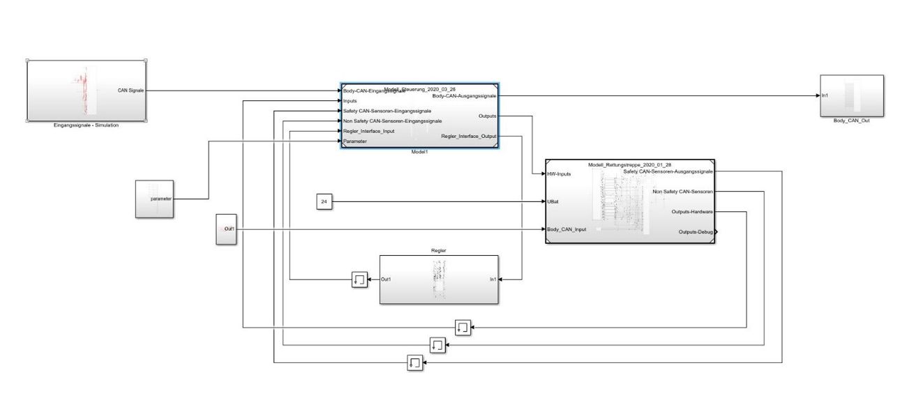
Figure 3. System-level model including plant and controller submodels.
Code Generation and HIL Testing
After verifying our early control design via desktop simulation, we moved quickly to HIL testing. We used Embedded Coder® to generate code from our plant model and deployed it to a TTC 580 ECU from TTControl. We followed a similar process to generate code from the controller model and deploy it to a second TTControl ECU. After wiring these two ECUs together exactly as the real controller would be wired into the rescue stairs, we ran HIL tests to validate the real-time performance of the control design and verify operation with the stairs’ touchscreen control panel (Figure 4).
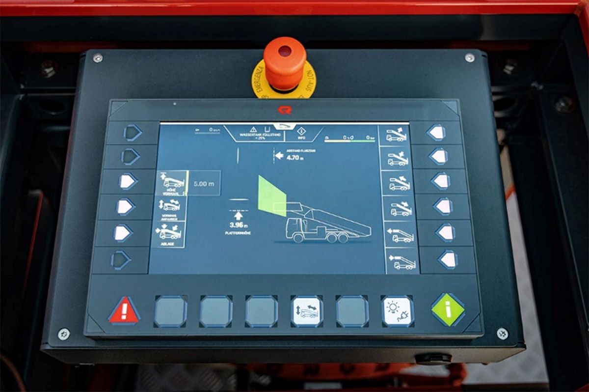
Figure 4. The 10-inch touchscreen display used for controlling the rescue stairs.
We also provided our colleagues who were working on the safety software at TTControl with an identical HIL testing setup. That team was then able to work in parallel with us, performing their own tests on the software they were developing without requiring access to the actual rescue stairs. This HIL testing setup not only enabled the TTControl team to accelerate the development of their software, it also helped them find and resolve several problems before any testing on the real stairs began.
On-Vehicle Tests and Commissioning
While the TTControl team finished development of the safety software, we continued to develop and refine the control application software. As part of this process, we imported C++ code for current and position control that was handwritten by TTControl engineers into our Simulink model using the Legacy Code Tool. We then continued to run simulations and HIL tests that verified not only new functionality that we were adding to the control application but also the C++ code developed and delivered by the other team.
At that point, we were ready to test our controller on the real rescue stairs. Again, we generated code from our Simulink model with Embedded Coder and deployed it to a TTControl ECU. This time, instead of wiring the ECU to the HIL setup, we connected it to the actual rescue stairs and ran a series of on-vehicle tests.
All the test cases that we verified via simulation also worked on the real stairs. We did find, however, a few corner cases—including odd combinations of button presses on the touchscreen display—that we had not considered beforehand. We resolved these issues by inserting additional states and transitions into our state machine in Stateflow (Figure 5). We then ran simulations to verify the changes, regenerated code, and tested once again on the real stairs to ensure everything worked correctly. In the past, when we wrote control code by hand, any kind of change that involved adding states and transitions took much longer to implement and debug.
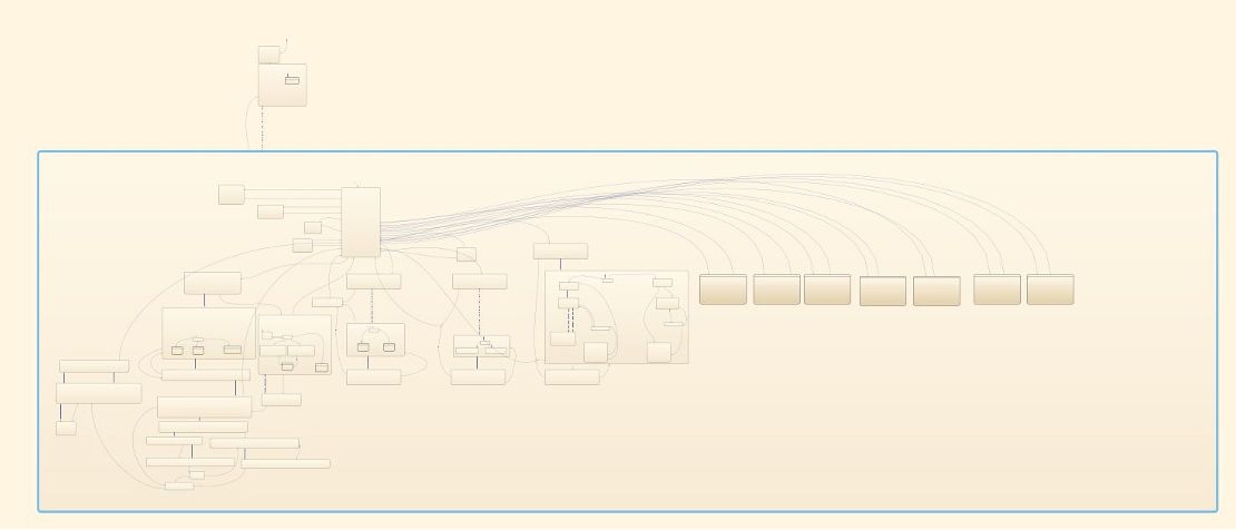
Figure 5. Overview of state machine designed with Stateflow.
Model-Based Design on Current Projects
With the rescue stairs now in production, we have taken stock of what we have achieved. In terms of performance, the stairs are capable of being extended to their topmost position about 20% faster than our previous design—increasing the speed of real-life rescues in emergency situations. From a development perspective, Model-Based Design enabled us to deliver a more reliable control system in about half the time that we would have needed with our previous approach.
A key factor in our increased development speed was the use of Embedded Coder to generate code from our Simulink model. We invested time in a training course on Embedded Coder to better understand how to utilize code generation. In addition to helping us make the most of the tool, this course also opened our eyes as to how easy it is to incorporate code generation into our workflow. We had been spending a significant amount of time debugging and maintaining handwritten code, and we were unaware that so many larger companies in the automotive industry were already using code generation for production control software. This realization, combined with our own firsthand experience on the rescue stairs, has led our team to extend the use of Model-Based Design to several other projects, including control design for an electric firefighting truck currently under development.
Related Training Course
Published 2023