Developing Advanced Emergency Braking Systems at Scania
By Jonny Andersson, Scania
Rear-end collisions are the most common type of accident for freight-carrying trucks and other heavy vehicles. To reduce the risk of rear-end collisions, in 2015 the EU mandated advanced emergency braking systems (AEBS) for all new vehicles.
Like other advanced driver assistance systems (ADAS), an AEBS uses input from sensors to screen the environment. When a collision is imminent, the system warns the driver with an audio alarm. If the driver does not respond, it applies a warning brake. If the driver still does not respond, the system applies the brakes fully to avoid the collision (Figure 1). The AEBS also provides “brake assist": When the driver brakes, but with insufficient force to avoid a collision, the system calculates and then applies the required extra braking force.

Figure 1. Top: AEBS overview. Bottom: A typical AEBS scenario, in which a truck with AEBS installed approaches a slow-moving vehicle.
AEBS uses both radar and camera sensors mounted on the front of the vehicle to scan for objects in the area ahead. The system leverages the particular strengths of each sensor to gain a more precise environment model. Radar sensors excel at determining an object’s range, relative velocity, and solidity but are less able to determine its shape or lateral position. A system using radar alone would find it difficult to distinguish a car parked at the side of the road from one in the driver’s lane. Cameras, on the other hand, can pinpoint an object’s size and lateral position but do not detect range well and are unable to assess density (a dense cloud may be perceived as a solid object).
My colleagues and I built a sensor fusion system that matches and merges data from both sensors into a single object. The system uses four weighted properties—longitudinal speed and position and lateral speed and position—to calculate the probability that both sensors have detected the same object. Once the sensor fusion system has identified an object in the host vehicle's path, it passes the object’s position and the vehicle’s projected path to the AEBS, which determines when to alert the driver or engage the brakes.
Our group had previously used Model-Based Design to develop an adaptive cruise control system using radar technology, but we had never before developed a sensor fusion system. Because it was a new design, we knew we would need a readable, understandable architecture to visualize signal flow. We also anticipated many design iterations, so we wanted an easy way to visualize results and debug our designs. In addition, we wanted to save time by generating code, but the code had to be efficient, as the CPU load on our electronics control unit (ECU) was already about 60% when we started the sensor fusion project. Lastly, we needed to thoroughly verify our design—our plan was to run simulations based on more than 1.5 million kilometers worth of sensor data. Model-Based Design met all these requirements.
Building the Sensor Fusion System
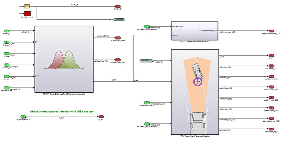
We began by partitioning the system design into functional units, such as object matching and projected path placement, and building a separate Simulink® block for each unit. The result was a clear software architecture with well-defined interfaces (Figure 2). We wrote MATLAB® code for the track association, to compute variances, calculate weighted probabilities, and perform other tasks that are easier to implement with a script than with blocks, and incorporated this code into our Simulink model with MATLAB Function blocks. These algorithm blocks made it easy for team members to merge their algorithms and integrate them with the control system.

Figure 2. Simulink model of the sensor fusion system showing independent functional blocks.
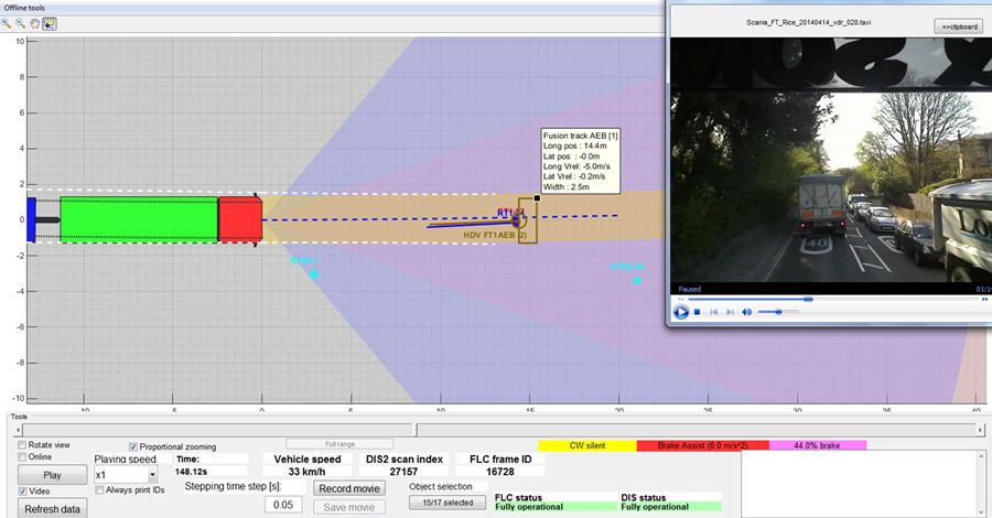
To debug and refine our initial design, we ran simulations using recorded radar sensor data, corresponding camera images, and other vehicle sensor data. During debugging we found it useful to visualize the sensor data alongside a camera view from the front of the vehicle. We built a visualization tool in MATLAB that displays sensor fusion data synchronized with a web camera view of the surrounding traffic (Figure 3). Taking advantage of the object-oriented programming capabilities of MATLAB, the tool uses a MATLAB class to represent each object detected by any sensor and the unified object perceived by the sensor fusion system. These MATLAB objects enabled us to quickly step forward and backward in time as we visualized the data.

Figure 3. Sensor visualization tool developed in MATLAB.
We used the same tool during road tests to visualize live data coming in from the vehicle network (Figure 4).

Figure 4. A controlled road test of the AEBS software. The trapezoidal object between the two vehicles is a “soft target” designed to resemble a vehicle that is used to “fool” the radar and the camera.
Implementing the System and Optimizing Performance
To deploy the sensor fusion system to the ECU, we generated C code from our Simulink model with Embedded Coder®. With code generation, we were able to get to an implementation quickly, as well as avoid coding errors. Most of the ECU processor’s resources were allocated to maintenance functions—monitoring dashboard alerts, physical estimations, data gateway, adaptive cruise control, and so on. As a result, we needed to optimize our initial design to increase its efficiency.
In order to get the most performance out of the generated code, we worked with the MathWorks pilot team, who helped us optimize code generated from MATLAB Coder. To further reduce the processing load we divided the model into separate parts that were executed on alternating cycles. For example, instead of running calculations for stationary and moving objects on every cycle, we ran them on alternating cycles. We realized that the processor was bogged down by the trigonometric functions our system was calling. To alleviate this problem, we wrote trigonometric approximation functions in C and called them from a MATLAB Function block. These modifications not only increased the efficiency of the sensor fusion code, they also enabled the AEBS software to react faster, which is vital when vehicles are traveling at highway speeds and every millisecond counts.
Verifying and Refining the Design
We tested the design in-vehicle on a closed course, but we needed to know how the system would react in real-world driving scenarios, such as different weather conditions, traffic patterns, and driver behaviors. It would be impractical as well as unsafe to test the AEBS directly under these conditions. Instead, we used a simulation-based workflow. We began by gathering data from a fleet of trucks. We decided to collect all data available on the ECU—not just data from the radar and camera used for sensor fusion—as well as images from a separate reference camera.
Using this fleet test data we ran simulations to identify interesting driving scenarios—scenarios in which the AEBS intervened to warn the driver or engage the brakes, and scenarios in which the system could have intervened but did not—for example, when the driver pressed the horn and braked simultaneously, swerved, or braked sharply. Focusing on these scenarios, we then analyzed the performance of the AEBS to identify areas in which we could improve the design.
We needed to resimulate every time we updated the AEBS software. However, with more than 80 terabytes of real traffic data logged over more than 1.5 million of kilometers of driving, it took several days to run a single simulation.
To accelerate the simulations, we built an emulator using code generated from our Simulink models with Embedded Coder. The emulator reads and writes the same MAT-files as our Simulink model but runs simulations 150 times faster. To further speed up simulations, we wrote MATLAB scripts that run simulations on multiple computers in our department as well as on dedicated multiprocessor servers, where we ran up to 300 simulations in parallel. With this setup, we cut the time needed to simulate all 1.5 million kilometers to just 12 hours. When we identified a new interesting scenario in the emulator, we reran the simulation in Simulink to analyze it in depth.
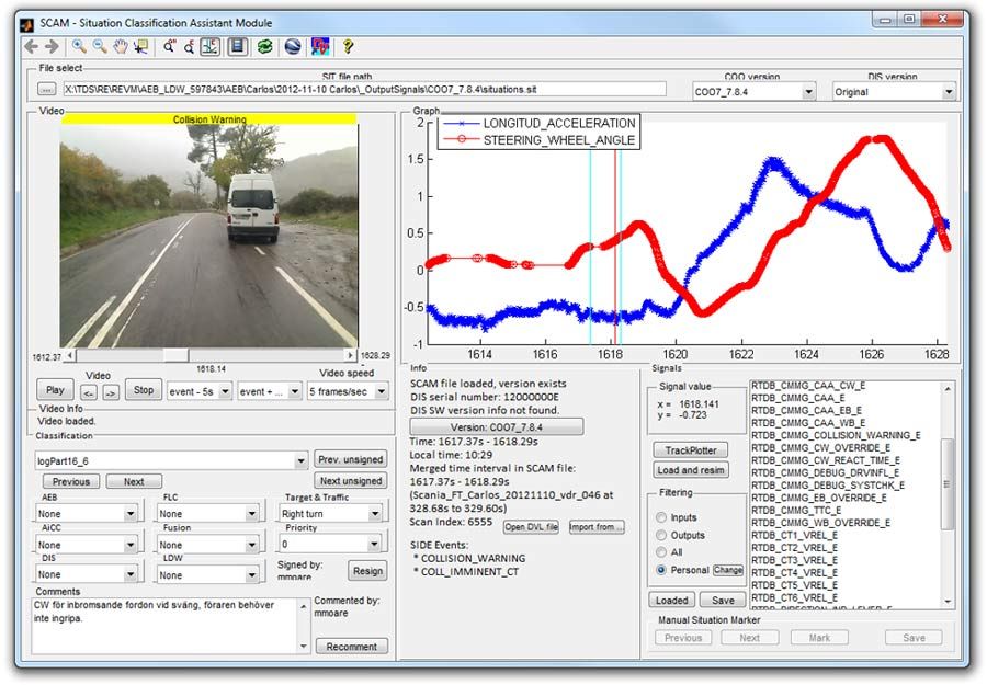
Identifying and classifying potentially interesting scenarios in terabytes of data was a tedious and time-consuming task, so we developed the Situation Classification Assistant Module, a MATLAB based tool that automates that part of the process (Figure 5). The tool generated a list of events from the simulations, such as collision warnings, warning brakes, and full brakes initiated by the system, as well as hard brakes and sharp turns initiated by the driver. We could then compare these lists for any two versions of our software.

Figure 5. The Situation Classification Assistant Module, a MATLAB based tool for processing logged ECU data and automatically identifying situations relevant to emergency braking.
The ability to perform extensive simulations enhanced the robustness and safety of the AEBS function and production code implementation for the ECU. It also enabled us to make changes more quickly. We had confidence in those changes because we were using all the available data in our simulations to test thousands of scenarios.
Deploying the Generated Code in Production ADAS
Most Scania trucks and buses are now equipped with AEBS running production code generated from Simulink models and verified via extensive simulations. We have reused our sensor fusion system design in Scania’s adaptive cruise control system, and there are now more than 100,000 units on the road.
Published 2016 - 93016v00