Early Verification of Digital-Analog Designs Using System-Level Cosimulation
By Hans-Werner Groh, Atmel and Thomas Janz, Atmel
The teams responsible for developing the digital baseband and the analog RF portions of an embedded electronic system are often literally worlds apart. At Atmel®, for example, our digital team is based in Ulm, while the analog team is based 150km away in Heilbronn.
In our previous design process, the separation was more than geographical. The RF front end and digital baseband were developed and simulated independently. This meant that we had no way to verify the complete system until we had actually fabricated the chip. Fixing problems discovered during post-silicon debugging required a respin, often adding months to the schedule and tens of thousands of Euros to production costs. The only sure way to address this problem was to improve our first-time-right silicon process.
To meet this objective, we implemented a design process in which we cosimulate digital baseband components in MATLAB® and Simulink® with the analog components in Cadence® Virtuoso® AMS Designer. This approach enables us to verify system performance during the design phase—well before we commit to silicon.
Developing Analog and Digital Components
The intention of the Atmel design flow is to use MATLAB models as the executable specification for the baseband and data processing part of the system. This executable specification guides the more detailed VHDL implementation and ultimately, the transistor-level implementation.
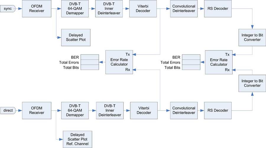
Atmel engineers have years of experience using MATLAB to develop complex baseband components, starting with the DVB-T demodulator shown in Figure 1, in which the OFDM demodulator, 64-QAM demapper, inner deinterleaver, Viterbi decoder, convolutional deinterleaver, and Reed-Solomon decoder were all designed and modeled in MATLAB and Simulink. For system verification the existing blocks were supplemented by a synchronization block.
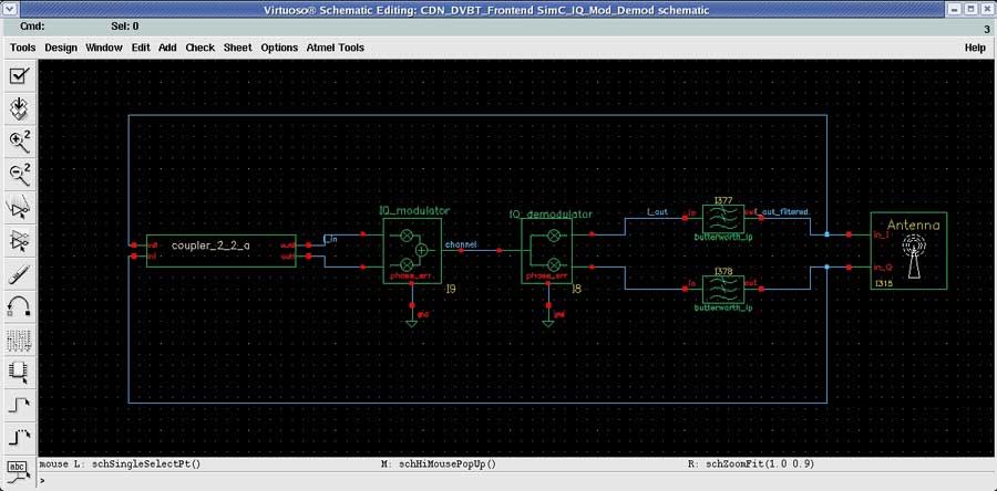
On the analog side, Atmel engineers use Cadence Virtuoso AMS Designer to design, simulate, and verify analog and mixed-signal components. The RF front-end of a DVB-T system is first modeled using behavioral blocks to enable rapid simulation. Later, these blocks are successively replaced,first with passband behavioral models and then with transistor-level models to increase model accuracy (Figure 2).
Developing the System-Level Model
Our designs often include analog blocks that are partially controlled by digital logic. For example, the analog design may include an automatic gain control with a gain factor generated by digital components. As a result, our system-level simulations must include this feedback loop from the digital to the analog domain. It is simply not possible to verify that these loops are working as intended without cosimulating the complete mixedsignal system.
Cadence Virtuoso AMS Designer Simulator provides a bidirectional link between Simulink and Cadence Virtuoso AMS Designer, enabling cosimulation and earlier verification of complex chip designs that combine analog and digital components.
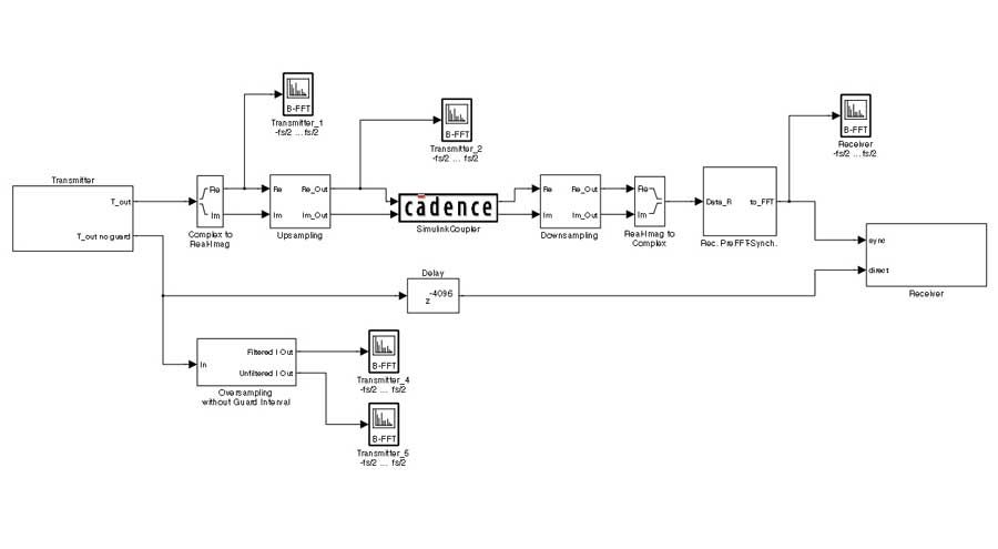
The cosimulation interface is implemented via coupler blocks. The Simulink coupler block, which we place in the Simulink model (Figure 3), represents the Virtuoso AMS Designer model of the RF front end.
Similarly, we place an AMS coupler block in the Virtuoso AMS Designer schematic editor to represent the Simulink model. These two coupler modules communicate with each other, enabling the cosimulation to take place on a single computer or on separate hosts (located in Ulm and Heilbronn,for example) and even on different operating systems. The coupler modules provide a user interface for configuring input and output parameters, the sampling mode, and network connection settings.
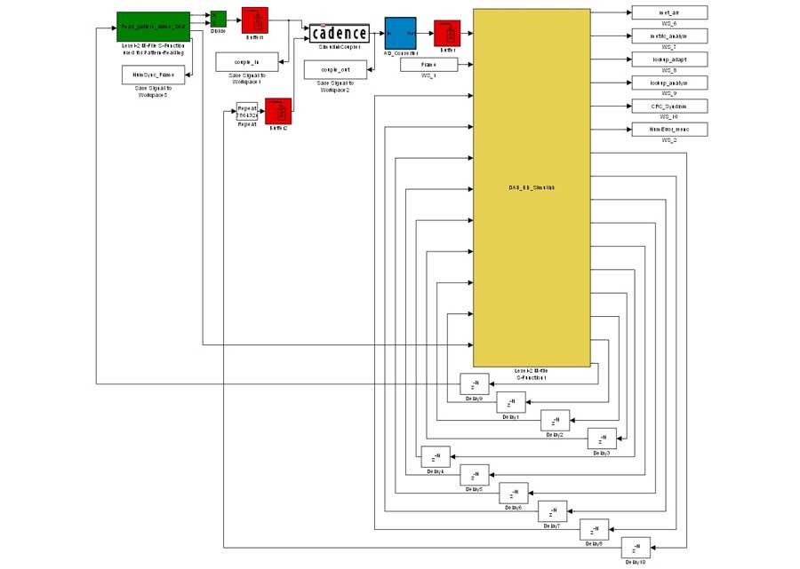
In the next step we used the experience gained for our MATLAB based DAB system. To create the system-level diagram in Simulink, we considered reimplementing our MATLAB algorithms for modulation, encoding, and so on as Simulink blocks. But the MATLAB implementations had been refined and optimized over a period of years, and the engineering team wanted to leverage this investment of time and effort and to keep the original MATLAB design flow unmodified as far as possible. Therefore we used the S-function API to create a custom Simulink block named DAB_BB_Simulink that incorporates these MATLAB algorithms (Figure 4).
This approach gives us reusable modules of proven MATLAB blocks that Atmel engineers can use to assemble and verify digital designs in the Simulink environment.
Synchronizing Domains
Synchronizing the two simulation domains in a cosimulation environment is a vital step. When using Cadence Virtuoso AMS Designer Simulator, Simulink serves as the primary controller of the cosimulation, determining the number and data types of the coupled signals as well as the length of the synchronization time intervals. When cosimulation is initiated, Simulink computes the input data for the coupler block and sends this data with a timestamp of the next sampling point to Virtuoso AMS Designer via the coupling interface. Virtuoso AMS Designer simulates the analog portion of the design up to this timestamp and then sends the resultant data back to Simulink, again via the coupling interface.
Choosing the sampling rate involves an engineering trade-off. As sampling rates increase, so do simulation times, and it takes longer to get results. Setting the sample rate too low, however, can cause rapid signal changes to be missed.
The Cadence Virtuoso AMS Designer Simulator cosimulation interface supports the different sampling modes available in Simulink and Signal Processing Blockset™, including fixed-step, variable-step, single-sample, and frame-based. Frame-based signals compose multiple samples into a single frame that can be transmitted all at once. This typically results in improved simulation performance because there is less communication between the connected blocks. After trying both sample-based and frame-based synchronization, we settled on the frame-based approach because of this performance advantage.
Simulating at the Right Level of Detail
Simulating at the transistor level takes too long for the kind of complex SoCs that we design at Atmel. On the other hand, simulating the entire system using only higher-level blocks does not provide the level of accuracy required to identify problems.
Cosimulation with MATLAB, Simulink, and Virtuoso AMS designer enables us to verify lower-level blocks in the context of a system-level simulation while maintaining acceptable simulation times. In fact,we can easily trade off accuracy for performance as needed by replacing selected parts of the system-level model with more detailed transistor-level blocks.
Furthermore, the cosimulation approach enables us to use our MATLAB algorithms in downstream design activities, bridging the gap between early-stage development and implementation. By incorporating our existing MATLAB algorithms as Simulink blocks, we enjoy many of the benefits of using Simulink as a testbench for mixed-signal design, including complex stimuli generation, signal visualization, and postprocessing.
We have already demonstrated the advantages of this approach on DAB and DVB-T projects at Atmel. We can use the same workflow on any project that combines an analog front end and digital processing. Using MATLAB and Simulink as a multidomain integration, development, and verification platform is a big step toward our goals of first-time-right silicon and no respins.
Published 2010 - 91808v00


