Implementing a Personnel Safety System for a Particle Accelerator Facility
By Paul Metcalf, Jefferson Lab
“We chose Simulink for this work because it provides a mature, fast, and well-supported way to model the graphical functions needed, and then verifies that designs are logically correct prior to implementation. In addition, Simulink Design Verifier allows us to achieve, among other requirements, 100% test coverage of all program functions and thus demonstrate that designs are safe.”
The Thomas Jefferson National Accelerator Facility (JLab) is a U.S. Department of Energy Office of Science national laboratory. It is a home to the Continuous Electron Beam Accelerator Facility (CEBAF), which produces an electron beam used to conduct fundamental research in nuclear physics. From start to finish, electrons travel up to five and a half laps around the facility’s racetrack design as they accelerate up to 12 billion electron volts (12 GeV).
To ensure risks to staff working at the facility have been minimized to “as low as (is) reasonably achievable” (ALARA), the JLab Safety Systems Group (SSG) designs, operates, and maintains an engineered Personnel Safety System (PSS). The PSS is responsible for a range of safety functions, including the prevention of direct exposure to prompt ionizing radiation.
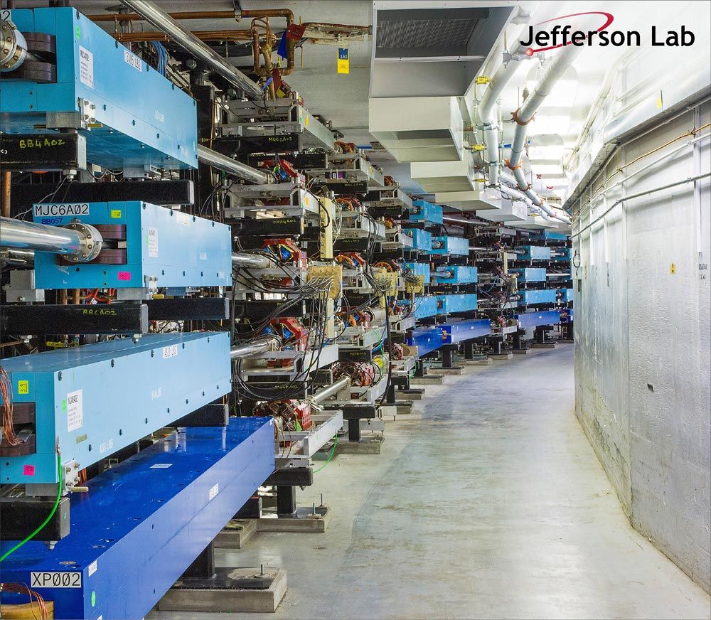
The PSS helps staff control entry to areas where safety hazards may exist. For instance, several significant safety hazards exist within the accelerator’s tunnel system while the beam is in operation. These include ionizing and non-ionizing radiation, laser radiation, and exposed high-voltage electrical conductors on the electromagnets used to recirculate the beam around the tunnel arcs (Figure 1). In the worst case, exposure to prompt ionizing radiation can result in a lethal dose within minutes. The PSS helps staff ensure that workers are cleared out of the accelerator’s tunnel system areas prior to beam operation and that staff members are then physically unable to enter those areas until beam operation is complete.
The PSS is currently undergoing a major upgrade that includes rewriting all software functions from the ground up. We selected a graphical language from IEC 61131 called Function Block Diagramming (FBD) to develop the software for the PSS.
Model-Based Design with Simulink® plays a central role in the implementation and verification workflows we are using to build the PSS software. All functions of the PSS are first modeled in Simulink and then simulated using test cases generated by Simulink Design Verifier™. We chose Simulink for this work because it provides a mature, fast, and well-supported way to model the graphical functions needed, and then verifies that designs are logically correct prior to implementation. In addition, Simulink Design Verifier allows us to achieve, among other requirements, 100% test coverage of all program functions and thus demonstrate that designs are safe.
It is a significant advantage to have the ability to complete all the required design, test, and safety lifecycle activities—including functional testing, arithmetic error checking (e.g., integer range violations), and coverage analysis—in a single environment.
Challenges of Scope and Complexity
The PSS is designed to detect and respond to two broad categories of Safety Integrity Level 3 risks: access control violations and beam control violations. These are essentially two sides of the same coin. While the initiating events differ, both types of violation result in a loss of separation between people and the beam. During an access control violation, if people enter an exclusion area within the facility, all hazards must be shut down within a few seconds (i.e., prior to any people reaching the lower levels of the tunnels). During a beam control violation, the beam may be missteered toward an accessible area or onto a beam-stopping device that is providing isolation for an accessible area. Due to the high power of the beam (1 million watts), the beam must be shut down in as little as a few milliseconds in this latter scenario.
The challenge of designing and verifying the PSS is compounded by the system’s complexity and scale. The PSS comprises over 2,200 I/O channels (including sensors and actuators) distributed around the facility’s nine segments. Segments are separated from one another by interlocked gates and doors. The PSS for each segment comprises a double-redundant safety system based on Siemens® 1500 Series safety PLCs.
Altogether, the system contains 18 distributed safety PLCs and 200 inter-PLC communication channels, which are used to exchange data. For every clock cycle, data from nearly 2,000 sensors is read and transmitted back to the main control center over fiber optic cables for processing. Once results are calculated, they are sent back out to the field to control the various warning and shutdown devices. This whole cycle is completed in as little as a few milliseconds and runs continuously. Around 50% of the code within the PSS is used for diagnostic and self-monitoring purposes (i.e., fault detection).
Any control system of this scope would require a substantial engineering investment. But safety systems can cost 3 to 10 times more than non-safety systems when implementing the same functionality. Targeting Siemens safety PLCs using the FBD language precluded the use of Simulink PLC Coder™ to generate IEC 61131 structured text directly from our Simulink models. Instead, all function blocks were first designed and verified in Simulink, before being manually reimplemented using the Function Block Diagram language in TIA Portal (the Siemens Integrated Development Environment used for PLC development and deployment) (Figure 2).
Figure 2. Designs are modeled in Simulink (first) before being implemented in TIA Portal (second).
Extending and Improving the Traditional Workflow
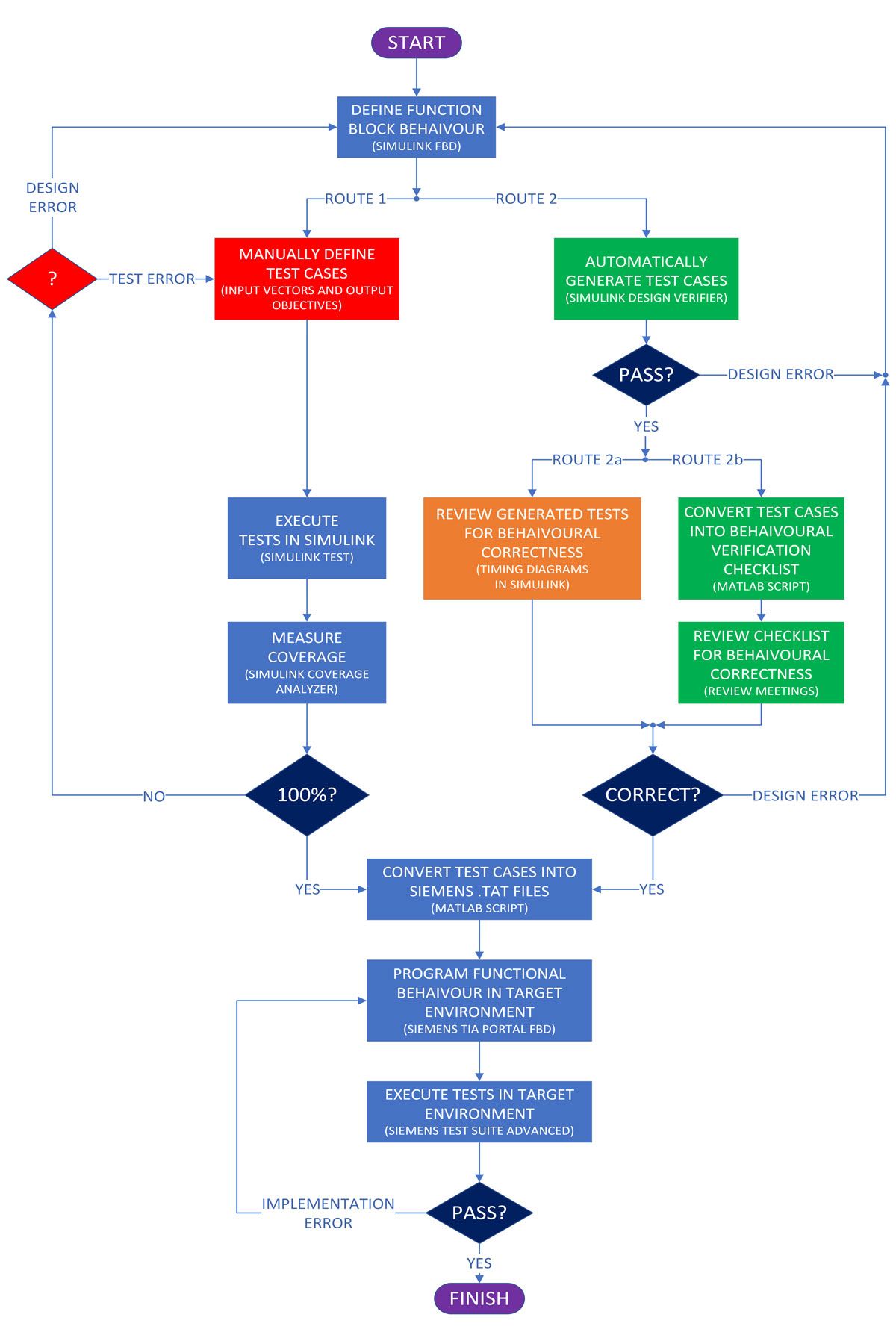
Given the scope and complexity of the PSS, we needed to look at how to optimize our existing development workflow. In the traditional workflow, once the behavior of a function block has been defined in Simulink, it would be necessary to define test cases in Simulink, including input vectors (stimuli) and output vectors (objectives). The test cases would be executed using Simulink Test™, and test coverage measured using Simulink Coverage™ (Figure 3, Route 1).
There are two key issues with this approach. Firstly, the task of manually generating test cases for every function can be exceptionally time-consuming, even for experienced test engineers. Secondly, if the tests do not achieve 100% coverage for the function under test, it can often be very difficult to determine if this is due to a design error in the function itself or a deficiency in the test method where more tests would need to be defined and executed.
To resolve these issues, we used Simulink Design Verifier to automatically generate test cases (using formal methods) that achieve 100% coverage. This eliminates the task of manually defining test cases. It also resolves the issue of how to detect design errors in the function under test. If Simulink Design Verifier cannot achieve 100% coverage, it highlights the location of the design error in the function itself. This workflow is a substantial improvement over the traditional method (Figure 3, route 2a).
While using Simulink Design Verifier provides substantial benefits, it introduces a new task to be performed. In the traditional method, the test engineer usually designs the desired functional behavior (objectives) implicitly into the test cases as they are developed. Provided the tests pass, the function is said to be behaving correctly. However, when using automatic test case generators, the formal algorithms do not have any knowledge of what is considered correct logical behavior. For this reason, it is necessary to review the test cases (and corresponding results) generated by Simulink Design Verifier for behavioral correctness—that is, to review the generated tests to verify that the function is behaving as intended.
This can be done either by reviewing the test cases (together with expected outputs) directly using timing diagrams or by simulating the test cases and observing the time-based simulation results on the model itself. Both options can be somewhat complicated and prone to error, particularly when functions have many inputs and outputs. Such testing requires an experienced test engineer with Simulink installed and can be prone to review blindness when there are many functions to review.
Since we were interested in having our design reviews performed by a group in a meeting-style environment, we are developing a concept called Behavioral Verification Checklists for verifying the behavioral correctness of our software functions. We created a MATLAB® script that converts the Simulink test cases into a procedural format to make them quicker and easier to read and interpret than traditional timing diagrams (Figure 3, route 2b).
A Closer Look at Behavioral Verification Checklists
A central aspect of our new workflow is the ability for engineers to review the behavioral correctness of function blocks using checklists rather than by reading timing diagrams or running simulations. These methods can often be time-consuming and prone to error, particularly when the number of I/Os is large. To address this, Behavioral Verification Checklists were developed to be concise and easily readable, focusing on the information that reviewers are most interested in. Engineers can use these checklists either independently or in groups to assess each functional block and how it responds to changes in input stimuli (Table 1), even if they do not regularly use Simulink or have it installed. This allows for the involvement of a greater number of subject matter experts in the design review process and reduces the burden on the test engineer. Since results are reviewed offline by multiple people, it increases the likelihood of detecting logical errors. The checklists are generated automatically using MATLAB scripts from Simulink test cases, which are in turn generated automatically using Simulink Design Verifier.
| STEP | TIME | INPUTS | OUTPUTS | CHECK |
|---|---|---|---|---|
| 1 | 0 |
|
TEST_OUTPUT = FALSE |
|
| 2 | 400 |
|
NO CHANGE |
|
| 3 | 600 |
|
NO CHANGE |
|
| 4 | 800 |
|
NO CHANGE |
|
| 5 | 1000 |
|
NO CHANGE |
|
| 6 | 1200 |
|
NO CHANGE |
|
| 7 | 1400 |
|
TEST_OUTPUT = TRUE |
|
| 8 | 1600 |
|
NO CHANGE |
|
| 9 | 2000 |
|
TEST_OUTPUT = FALSE |
Importing Simulink Test Cases into TIA Portal
In the final section of our workflow, we reimplement and test the function blocks in our target PLC environment. We begin by using a second MATLAB script to convert the Simulink test cases into Siemens test case files (which are text files with a .TAT extension) (Figure 4). We also translate the function block designs from Simulink into TIA Portal. Finally, we execute the converted test cases on the PLC code using Siemens PLCSIM and Test Suite Advanced to ensure equivalency on the target.
TEST_CASE “TEST_OUTPUT_TEST_CASE_1”

PROPERTY
AUTHOR : “METCALF”
VERSION : “1.0”
COMMENT : “Test Case 1 for TEST_OUTPUT function block.”
SCOPE : “PSS_PLC”
END_PROPERTY

VAR
TEST_INITIAL_CONDITIONS : TEST_OUTPUT_IDB.TEST_INITIAL_CONDITIONS := FALSE;
TEST_CONFIGURED : TEST_OUTPUT_IDB.TEST_CONFIGURED := TRUE;
TEST_REQUESTED : TEST_OUTPUT_IDB.TEST_REQUESTED := FALSE;
TEST_CONTINUOUS_CONDITIONS : TEST_OUTPUT_IDB.TEST_CONTINUOUS_CONDITIONS := TRUE;
MINIMUM_TEST_DURATION : TEST_OUTPUT_IDB.MINIMUM_TEST_DURATION := T#74ms;
TEST_OUTPUT : TEST_OUTPUT_IDB.TEST_OUTPUT;
END_VAR

STEP : “STEP_1”
RUN(CYCLES := 1);
ASSERT.Equal(TEST_OUTPUT,FALSE);
RUN(CYCLES := 399);
END_STEP

STEP : “STEP_2”
TEST_CONFIGURED := FALSE;
TEST_CONTINUOUS_CONDITIONS := FALSE;
MINIMUM_TEST_DURATION := T#0ms;
RUN(CYCLES := 1);
ASSERT.Equal(TEST_OUTPUT,FALSE);
RUN(CYCLES := 199);
END_STEP

STEP : “STEP_3”
TEST_REQUESTED := TRUE;
RUN(CYCLES := 1);
ASSERT.Equal(TEST_OUTPUT,FALSE);
RUN(CYCLES := 199);
END_STEP
. . .
. . .
. . .
END_TEST_CASE
Figure 4. Portion of a Siemens test case generated by a MATLAB script from a Simulink test case.
Deployment and Applying the Workflow to Other Projects
High-integrity safety systems like the PSS require strict development workflows to minimize the risk of software errors contributing to unsafe—and potentially even catastrophic—consequences. When duplicating software components across redundant processing units, those risks are further multiplied since any error will become Common Cause (CC). For these reasons, IEC 61508 places a strong emphasis on the avoidance of systematic faults being introduced into safety systems through software. With Model-Based Design and our new workflow, we have achieved an increase in our Systematic Capability—as defined in IEC 61608—to a level that provides a very high level of assurance that we have implemented a safe and error-free system.
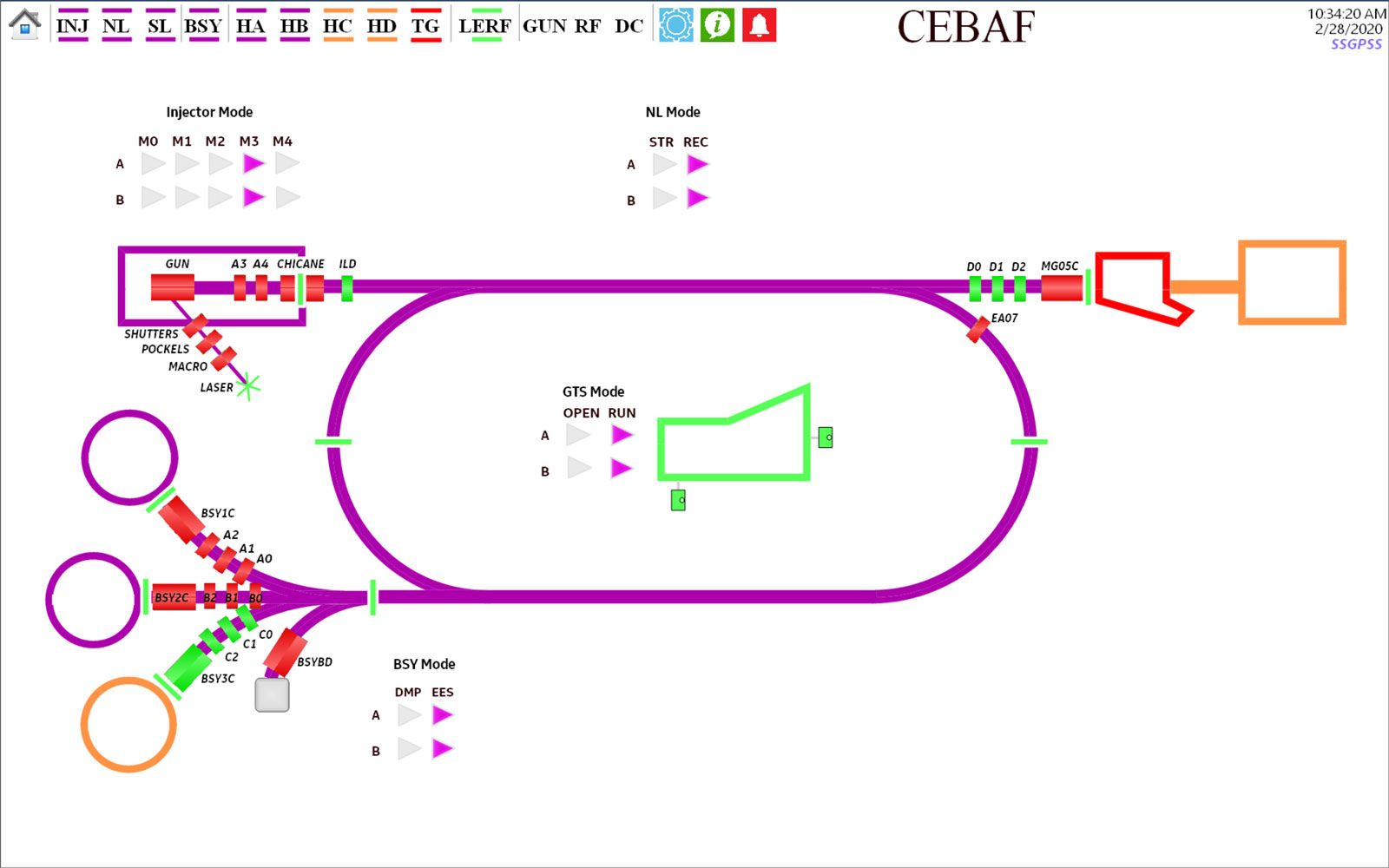
We are currently in the final stages of deploying the upgraded PSS to the last remaining accelerator segments (Figure 5), with an expected completion date in the fall of 2024. After completing the PSS, one of our next development priorities will be upgrading our Beam Loss Monitoring (BLM) system, which is part of our Machine Protection System. For this project we intend to use a workflow very similar to the one used for the PSS. However, given that the target for the BLM system will be an FPGA, we plan to use HDL Coder™ to generate synthesizable HDL code directly from our Simulink models and avoid manual coding on the target almost entirely. We also hope to use the hardware-in-the-loop capabilities of HDL Verifier™ to simplify and accelerate our on-device verification and validation workflow.
Published 2024


