Implementing a Hybrid Vehicle-in-the-Loop Testing Methodology for Automated Driving Functions
By Selim Solmaz, Virtual Vehicle Research GmbH
“Model-Based Design … made it possible to concentrate our efforts on validating hybrid testing as an approach rather than low-level coding and implementation details.”
Advanced driver assistance systems (ADAS) and automated driving (AD) systems require extensive testing across a diverse range of driving scenarios before they can be safely used in production vehicles. This testing can present a significant challenge for automotive engineers due to the limitations of the two broad approaches commonly used today. The first approach, which involves testing AD and ADAS functionality through simulation only, is effective for early algorithm development but fails to capture real vehicle dynamics and hardware-related effects that can substantially affect algorithm performance. While conducting tests in a real vehicle eliminates these limitations, this second approach is more time-consuming, costly, and difficult to replicate—not to mention potentially unsafe for certain driving scenarios.
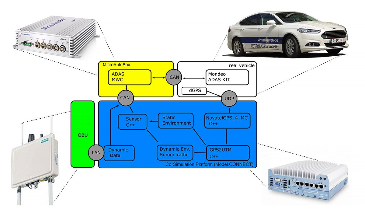
To bridge the gap between simulation-only and in-vehicle testing, my team at Virtual Vehicle Research has implemented a hybrid testing approach. This approach is defined by incorporating vehicle-in-the-loop tests that combine a real vehicle with virtual vehicles in a cosimulation framework, enabling safe, realistic testing of ADAS and AD functionality in simulated traffic scenarios (Figure 1). In a sudden braking scenario, for example, this hybrid testing approach can be applied to run tests of an automatic emergency braking system that fully accounts for the real vehicle’s mass, braking system dynamics, hardware delays, and other nuances that are very difficult or impossible to capture in models—all without risking a real-world rear-end collision.
Figure 1. The cosimulation framework enables safe, realistic testing of ADAS and AD functionality.
We validated our hybrid testing methodology by testing ADAS capabilities developed in-house using Model-Based Design with MATLAB® and Simulink®. These capabilities incorporate lateral and longitudinal tracking as well as lane-change decision functions to support adaptive cruise control (ACC), lane-keeping assistance (LKA), and trajectory planning (TP) features. Model-Based Design enabled us to rapidly model, simulate, and generate code for ADAS functions, which made it possible to concentrate our efforts on validating hybrid testing as an approach rather than low-level coding and implementation details.
How Hybrid Testing Works
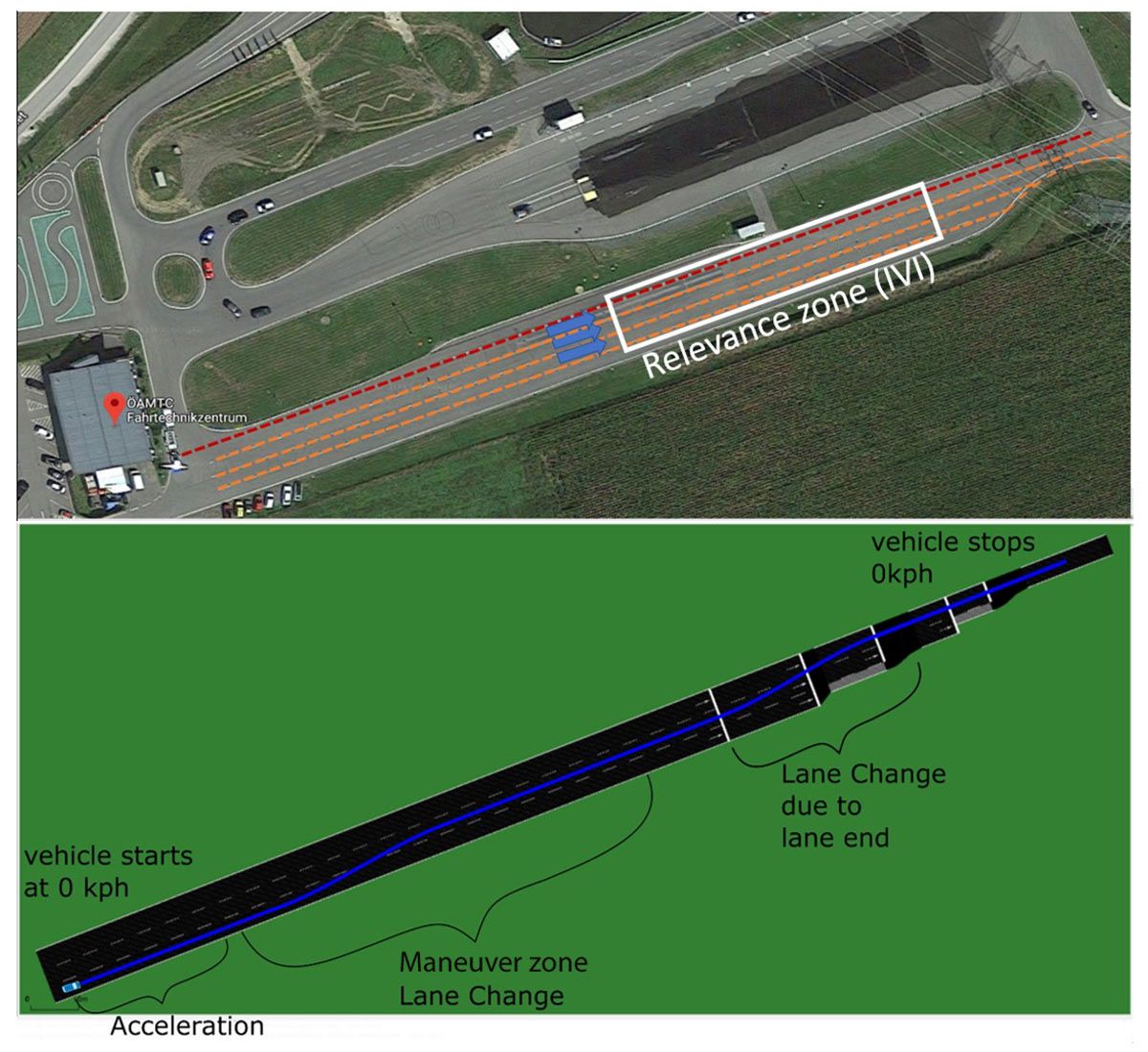
In hybrid testing, a real vehicle equipped with AD or ADAS software and hardware operates on an enclosed proving ground that is free of any other vehicles or obstacles. Instead of sensing and responding to real-world traffic, the control software interacts with a virtual environment that is continuously updated in real time as the vehicle moves across the proving ground. In our setup, the test vehicle is a Ford® Mondeo Hybrid equipped with an ADAS kit that allows full control of the vehicle’s throttle, brake, steering, and shifting. The proving ground is the ÖAMTC Lang/Lebring test track near Graz, Austria (Figure 2). Additionally, the virtual environment is based on Simulation of Urban MObility (SUMO), an open-source, continuous traffic simulation package, with the static environment—including road signs, lane coordinates, and other infrastructure elements—defined using the ASAM OpenDRIVE® format specification.
As the test vehicle moves on the multilane track, its position, speed, and orientation are captured via GPS and other onboard sensors. This information is relayed to the virtual environment running on an industrial PC in the vehicle, where it is used to orient the test vehicle (ego vehicle) within the traffic simulation. Based on the simulation of the ego vehicle and its position relative to virtual vehicles and static infrastructure elements, the virtual environment generates a set of object lists and lane detection information, which is sent via a CAN bus interface to the ADAS control software running on dSPACE® MicroAutoBox real-time hardware. The control software uses the object lists and lane information to make decisions on braking, acceleration, lane changes, and trajectory planning, before sending the signals required to carry out those decisions to the vehicle’s steering, throttle, and brake actuators via the CAN bus (Figure 3).
Modeling, Simulating, and Generating Code for ADAS Functions
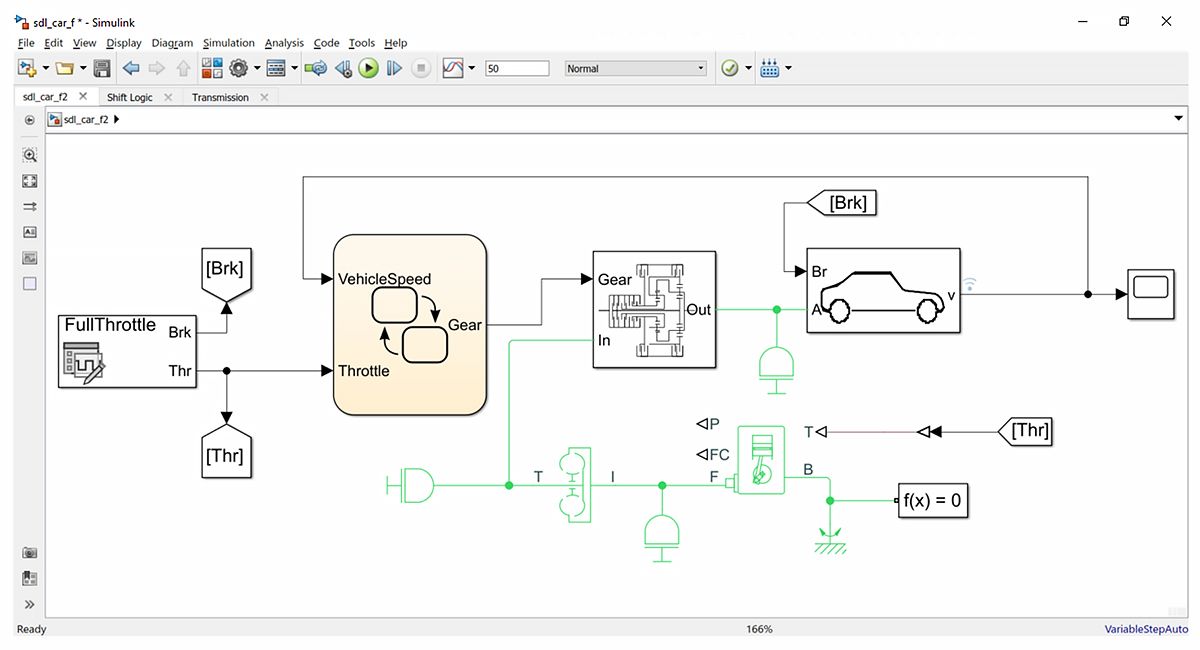
We began developing the ACC, LKA, and trajectory planning components of our ADAS function—which we dubbed Motorway Chauffeur (MWC)—using a set of Simulink models developed by our colleagues for another ADAS application. We adapted these models to use the object lists and lane information coming from the virtual environment and ran a series of closed-loop simulations on the desktop to verify the system’s basic functionality (Figure 4). We also ran simulations of our ADAS control models with IPG CarMaker using the Model.CONNECT integration platform.
Once we had tested our ADAS functions via simulation, we used Embedded Coder® to generate C++ code from our models and then deployed the code to the MicroAutoBox target hardware in preparation for in-vehicle tests.
Conducting In-Vehicle Tests and Post-Processing Results
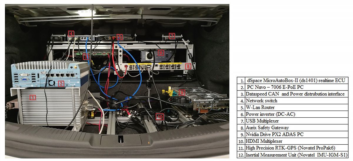
We installed the entire hardware setup, including the MicroAutoBox hardware and industrial PC, in the test vehicle (Figure 5). With this configuration, we conducted numerous tests on the proving ground to evaluate a variety of ADAS and AD functions, including lane changes and velocity changes in response to infrastructure-to-vehicle information messages (IVIM) in the presence of virtual traffic.
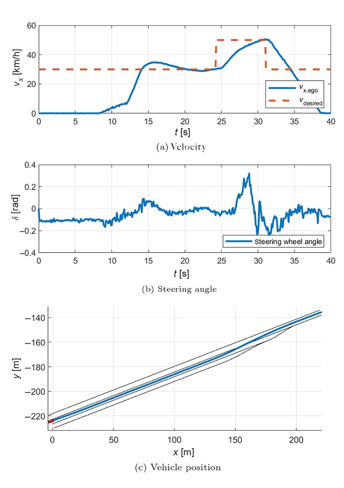
After the test drives, we used MATLAB to analyze data recorded by onboard sensors and to generate plots that showed the vehicle’s velocity, steering angle, and position over time (Figure 6). This analysis was central to our research goals, as it enabled us to use the vehicle-in-the-loop tests to evaluate key performance indicators (KPIs) of the ADAS functionality.
Postprocessing data in MATLAB was also instrumental in analyzing issues that we discovered during our tests. For example, in one test we replaced the object-list data coming from the virtual environment with similar data coming directly from a MobilEye ADAS camera. When swapping the simulated data with data from the real sensor, we noticed oscillations in the control signals. Our analysis revealed that the problem stemmed from a delay of approximately 300 milliseconds in the lane detection data. After introducing this same delay in our Simulink model, subsequent simulations showed similar oscillations. We could then modify our control algorithm to account for this delay, and regenerate code to resolve the problem.
Next Steps
Our team is continuing to develop the hybrid testing methodology we have implemented. We are currently exploring several enhancements, including the use of 3D visualizations for traffic scenarios in place of the current bird’s-eye-view visualizations. Another planned enhancement is the inclusion of physical sensor models in the simulation framework, which will support the development and vehicle-in-the-loop testing of perception algorithms and enable the further integration of onboard sensors in hybrid testing.
Published 2024
