Modeling Industrial Chemical Processes with MATLAB and Simulink at HUGO PETERSEN GmbH
By Ahmad Fani Yazdi, HUGO PETERSEN GmbH
Sulfuric acid is used in the manufacture of fertilizers, petrochemical products, synthetic fiber, steel, and a wide range of other industrial materials. Used acid and waste gases are recycled in processing plants that must meet stringent safety and environmental requirements for working with these chemicals.
HUGO PETERSEN GmbH has a decades-long track record of engineering safe and efficient sulfuric acid and gas cleaning plants. Until recently, however, our development process was highly labor-intensive. All preliminary design work and process modeling was done using a complex system of spreadsheets. This manual approach slowed development and introduced the potential for human error.
Model-Based Design with MATLAB® and Simulink® has provided a cost-effective way to simplify and automate our design workflow by enabling chemical process engineers and controls engineers to work in the same environment. While the chemical process engineers model the complex thermodynamic and kinetic interactions within the plant, controls engineers model the control algorithms. The plant and its control system can then be tested in dynamic and steady-state closed-loop simulations.
The new approach is 5 to 10 times faster than the spreadsheet-based approach, and much less susceptible to human error.
Too Complex for Spreadsheets
A typical sulfuric acid plant includes numerous subsystems, such as chemical reactors, heat exchangers, and absorption towers. Calculating the thermodynamic and kinetic interactions within each subsystem is inherently difficult. Capturing these processes in spreadsheets compounded the challenge. Many manual steps were required: The outputs from one subsystem had to be copied to a new spreadsheet for use as input to the next step in the process, and so on. A single error at one stage could throw off the results for the entire process. With so many interconnected spreadsheets, it was difficult to identify and fix such errors.
Creating a Library of Subsystem Models
The first step in the new workflow was to create a library of reusable modules, one for each subsystem, which the chemical process engineers could then combine in Simulink system models. To manage the overall complexity of our designs, we defined each module as a MATLAB class, enabling us to apply object-oriented design patterns to the development of the entire library.
An absorption tower, for example, is defined as a MATLAB class, as are the fluid and gas streams that it takes as input. In the actual tower, the gas enters at the bottom of a column and is partially absorbed by the liquid, which enters through the top of the tower and runs down through the column. We modeled the thermodynamic and kinetic processes in MATLAB using the classes we had developed.
The classes perform all the operations that were previously done in spreadsheets, as well as several new calculations that were enabled by the switch to MATLAB—for example, calculation of the heat generated by the absorption of SO3 in different concentrations of sulfuric acid. The outputs of the absorption tower model, one gas object and one fluid object, capture the results and are used as input to the next subsystem in the plant. Our process engineers can use the blocks by simply dragging and dropping them into the Simulink environment, but they can also study the underlying MATLAB code and develop new MATLAB classes, as well as create new libraries in Simulink.
Simulating Chemical Processes
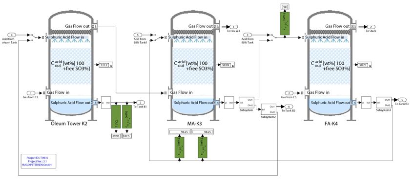
Using a library of MATLAB models for the key plant subsystems, our chemical process engineers can quickly build larger plant designs in Simulink and simulate them. Several absorption towers, for example, can be connected in Simulink to form a larger absorption unit (Figure 1).
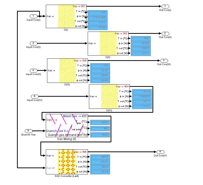
Using the subsystem blocks in the library, the engineers can rapidly design and simulate sophisticated new plants, assess changes to existing plants, or evaluate new processes. For example, they might link two chemical reactors and a static mixer for quench gas (Figure 2). Sensors can be included to monitor temperature, pressure, flow, and other variables throughout the simulation.
Simulations enable the engineers to visualize key aspects of the process (Figure 3) and help ensure that it complies with environmental regulations. For example, if the air has not been treated sufficiently to meet regulatory standards, this condition is flagged with a red marker, which indicates that further treatment or other changes to the process may be required.
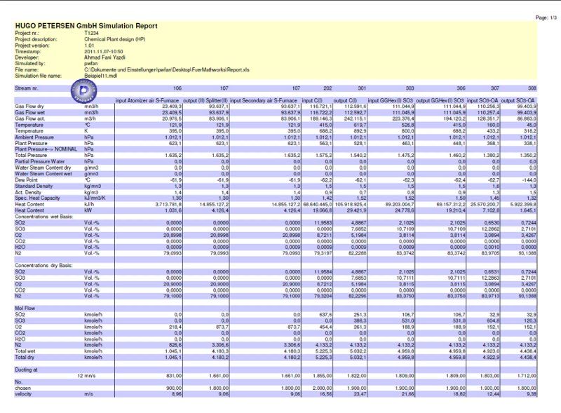
Once the chemical process engineers have designed, simulated, and verified the entire process in Simulink, they use Spreadsheet Link™ EX to export the simulation results to a Microsoft® Excel® spreadsheet (Figure 4). This report typically includes the dimensions of the various subsystems, as well as flow rates, temperatures, and pressures at key points in the process. It is shared with the HUGO PETERSEN customer who initiated the project, the construction team that will build the plant, and the suppliers who will provide components. A supplier of blowers, for example, can determine the size and type of blower needed by extracting the relevant flow rate and gas density from the report.
Simulating Control Systems and Plant Startups
To verify the control algorithms, engineers combine the control system model with the plant model and run closed-loop simulations. These simulations enable both teams to assess the steady-state and dynamic performance of the entire plant. They can simulate startup and shutdown procedures, as well as faults and hazardous conditions that would be difficult or unsafe to test on an actual plant.
We continue to use the system model during the plant startup process. If the onsite field engineers need to know how the plant will behave under specific conditions, we run a simulation back at the office and send them the results. This greatly reduces the risk inherent in startups because the team knows that the steps they are about to perform will work as expected.
From Ideas to Production
Model-Based Design with MATLAB and Simulink has enabled us to evaluate many design ideas for each project. Because the designs we create are flexible, we can quickly respond to changing customer requirements. The shared environment has improved communication between the control and chemical process engineers, making it easy to collaborate to solve problems and optimize performance.
Overall, MATLAB and Simulink have enabled us to cut costs and reduce development time by a factor of 5 to 10. We have designed and simulated systems—including the largest oleum plant in the world—that were far too complex to handle with our spreadsheet-based approach. Just as importantly, quality has increased, as we now can find and eliminate errors much faster.
This approach has made it easier to demonstrate plants and new design concepts to our customers. We can simulate a model of a production plant and show that the simulation results match the actual performance of the plant. This gives new customers a great deal of confidence in our ability to design and deliver a plant to their specifications.
Published 2012 - 91988v00


