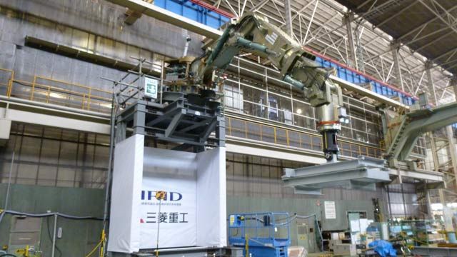
Mitsubishi Heavy Industries Develops Robotic Arm for Removing Nuclear Fuel Debris
“Model-Based Design with MATLAB and Simulink supports a wide range of options, from classic to modern control, which made it possible to respond easily to any changes in design constraints and to meet the demanding accuracy requirement for this robot.”
Challenge
Design a multi-axis robot for removing molten fuel debris from the Fukushima Daiichi nuclear power station
Solution
Use MATLAB and Simulink to perform hardware measurement tests and to model and simulate individual robot axes and controllers
Results
- Development time halved
- Positioning accuracy requirement exceeded
- Shared platform for interorganizational collaboration established

Rendering of Mitsubishi Heavy Industries’ seven-meter-long robotic arm capable of withstanding up to 2000 kg of processing reaction force.
Following the accident at the Fukushima Daiichi nuclear power station, the Japanese government launched a years-long effort to stabilize and decommission the facility. One of the greatest technical challenges of this effort, which is directed in part by the International Research Institute for Nuclear Decommissioning (IRID), is the safe removal of molten fuel debris and internal furnace structures.
To enable debris removal, Mitsubishi Heavy Industries (MHI) is building a seven-meter-long robotic arm capable of withstanding up to 2000 kg of processing reaction force. Designed and verified in Simulink®, the robot’s hydraulic control system can move the arm’s six axes to achieve a positioning accuracy at the tool tip of just 5 mm—well within the IRID requirement of 10 mm.
“Working on a project such as this without Model-Based Design often entails trial-and- error methods, leading to major refactoring work performed under cost and time pressure,” says Tadashi Murata, engineer at Mitsubishi Heavy Industries. “Using MATLAB and Simulink in the initial phases of the project helped us to identify issues early. As a result, we were able to halve the time spent on development and debugging on the actual device.”
Challenge
Conditions inside the nuclear power station had changed significantly since the station was built. Lack of information on the current conditions made it difficult to develop specifications for the robotic arm. Because the design constraints were not clear at the outset, the MHI team needed to run numerous simulations and hardware-in-the-loop (HIL) tests to refine and verify the control design.
Both the size of the robot and the hydraulic drive system planned for the arm were without precedent at MHI. Whereas construction-site excavator booms have four axes (one rotational and three bending), the robotic arm has six (three rotational and three bending) to enable positioning of the tool tip to within 10 mm of its target. The robot’s extraordinary size and hydraulic configuration, combined with the risks associated with testing insufficiently validated control algorithms on such equipment, underscored the need for extensive modeling and simulation for the control design.
Solution
MHI engineers used Model-Based Design with MATLAB® and Simulink to develop and verify the robotic arm’s control software.
After creating a design outline based on the requirements specification, the MHI team conducted hardware tests of the rotating and bending axes, measuring factors such as non-linearity, responsiveness, and the effects of friction resistance. To automate these measurements, the team developed a test control system using MATLAB, Simulink, and a real-time Linux® platform.
Working in Simulink, the team built a single-axis model—including hydraulic cylinders and servo valves—based on measurement data collected during the hardware tests.
Using Simulink and Control System Toolbox™, the team developed a two-degree-of-freedom PID control model. This model incorporates hydraulic control techniques such as differential pressure feedback, as well as robotic control techniques such as gravity compensation.
They conducted simulations in Simulink to tune controller gains, determine the torque required to maintain position, and check the implementation of the gravity compensation algorithms.
Following these simulations, the team constructed a complete robot model in Gazebo and conducted HIL tests. The Gazebo robot model and Simulink controller model were connected using ROS. Next, they performed full functional tests of the robot to verify its moveable range, positioning accuracy, and excavation capacity, using MATLAB to analyze the test results.
The project is on target for the scheduled commencement of fuel extraction work at Fukushima. MHI plans to reuse models and simulations from this work on future hydraulic manipulators that require both highly accurate positioning and the capacity to carry heavy loads.
Results
- Development time halved. “To meet the deadline for fuel extraction imposed by the national road map, the control development schedule was set at six months, a timeframe we initially thought was too short,” says Murata. “With Model-Based Design we were, in fact, able to cut that development time to just three months.”
- Positioning accuracy requirement exceeded. “Our system has to perform with a high degree of accuracy; the requirement is to position the tool tip to within 10 mm with a load of 500 kg,” says Murata. “The simulations and tests we performed in Simulink enabled us to exceed this goal and achieve an accuracy of 5 mm.”
- Shared platform for interorganizational collaboration established. “During the project, we consulted with and received valuable advice from a research group at Osaka University,” says Murata. “Using Simulink as our common language in discussions of the control design enabled all of us to quickly form a shared understanding of the algorithms and the design.”