DL-SCH 和 PDSCH 发送和接收处理链
此示例展示了如何使用 5G Toolbox™ 功能对 5G NR 物理下行链路共享信道 (PDSCH) 链路进行建模,包括从传输块生成到接收机端比特解码的所有步骤。
简介
下图显示了下行链路共享信道 (DL-SCH) 和 PDSCH 发送和接收处理链。

此示例展示了如何对链路级仿真的这些元素进行建模。
DL-SCH 编码
混合 ARQ (HARQ) 管理
PDSCH 编码
多输入多输出 (MIMO) 预编码
OFDM 调制
传播信道和加噪
定时同步
OFDM 解调
信道估计与均衡
PDSCH 解码
DL-SCH 解码
有关如何使用链路级仿真来测量吞吐量的示例,请参阅 NR PDSCH 吞吐量。
仿真参数
指定信噪比 (SNR)、要仿真的时隙数和完美信道估计标志。若要详细了解此示例中使用的 SNR 定义,请参阅SNR Definition Used in Link Simulations。
SNRdB = 10;                % SNR in dB
totalNoSlots = 20;         % Number of slots to simulate
perfectEstimation = false; % Perfect synchronization and channel estimation
rng("default");            % Set default random number generator for repeatability
载波配置
创建一个载波配置对象。此对象可控制参数集,例如子载波间隔、带宽和循环前缀 (CP) 长度。此示例使用默认属性集。
carrier = nrCarrierConfig
carrier =
  nrCarrierConfig with properties:

                NCellID: 1
      SubcarrierSpacing: 15
           CyclicPrefix: 'normal'
              NSizeGrid: 52
             NStartGrid: 0
                  NSlot: 0
                 NFrame: 0
    IntraCellGuardBands: [0×2 double]

   Read-only properties:
         SymbolsPerSlot: 14
       SlotsPerSubframe: 1
          SlotsPerFrame: 10
PDSCH 和 DM-RS 配置
创建一个 PDSCH 配置对象。指定调制方案 (16-QAM) 和层数 (2)。将所有资源块 (RB) 分配到 PDSCH(全频段分配)。您还可以在此对象中指定其他时间分配参数和解调参考信号 (DM-RS) 设置。
pdsch = nrPDSCHConfig;
pdsch.Modulation = "16QAM";
pdsch.NumLayers = 2;
pdsch.PRBSet = 0:carrier.NSizeGrid-1;     % Full band allocation
显示 PDSCH 参数。
pdsch
pdsch =
  nrPDSCHConfig with properties:

                NSizeBWP: []
               NStartBWP: []
             ReservedPRB: {[1×1 nrPDSCHReservedConfig]}
              ReservedRE: []
              Modulation: '16QAM'
               NumLayers: 2
             MappingType: 'A'
        SymbolAllocation: [0 14]
                  PRBSet: [0 1 2 3 4 5 6 7 8 9 10 11 12 13 14 15 16 17 18 19 20 21 22 23 24 25 26 27 28 29 30 31 32 33 34 35 36 37 38 39 40 41 42 43 44 45 46 47 48 49 50 51]
              PRBSetType: 'VRB'
    VRBToPRBInterleaving: 0
           VRBBundleSize: 2
                     NID: []
                    RNTI: 1
                    DMRS: [1×1 nrPDSCHDMRSConfig]
              EnablePTRS: 0
                    PTRS: [1×1 nrPDSCHPTRSConfig]

   Read-only properties:
            NumCodewords: 1
设置 DM-RS 参数。要改进信道估计,请添加一个额外的 DM-RS 位置。
pdsch.DMRS.DMRSAdditionalPosition = 1;
设置 DM-RS 配置类型和 DM-RS 长度,这决定了正交 DM-RS 序列或 DM-RS 端口的数量。
当
DMRSLength = 1时,DMRSConfigurationType = 1最多支持 4 个 DM-RS 端口。当
DMRSLength = 2时,DMRSConfigurationType = 1最多支持 8 个 DM-RS 端口。当
DMRSLength = 1时,DMRSConfigurationType = 2最多支持 6 个 DM-RS 端口。这是针对多用户 MIMO (MU-MIMO) 设计的。当
DMRSLength = 2时,DMRSConfigurationType = 2最多支持 12 个 DM-RS 端口。这是针对 MU-MIMO 设计的。
最大层数必须小于或等于 DM-RS 端口数。
pdsch.DMRS.DMRSConfigurationType = 1;
pdsch.DMRS.DMRSLength = 2;
pdsch.DMRS                            % Display DM-RS properties
ans =
nrPDSCHDMRSConfig with properties:
DMRSConfigurationType: 1
DMRSReferencePoint: 'CRB0'
DMRSTypeAPosition: 2
DMRSAdditionalPosition: 1
DMRSLength: 2
CustomSymbolSet: []
DMRSPortSet: []
NIDNSCID: []
NSCID: 0
NumCDMGroupsWithoutData: 2
DMRSDownlinkR16: 0
DMRSEnhancedR18: 0
Read-only properties:
CDMGroups: [0 0]
DeltaShifts: [0 0]
FrequencyWeights: [2×2 double]
TimeWeights: [2×2 double]
DMRSSubcarrierLocations: [6×2 double]
CDMLengths: [2 1]
DL-SCH 配置
指定编码率、HARQ 进程数和冗余版本 (RV) 序列值。此序列控制出错时的 RV 重传。要禁用 HARQ 重传,可以将 rvSeq 设置为一个固定值(例如 0)。有关如何使用 HARQ 对传输信道进行建模的详细信息,请参阅对具有 HARQ 的 5G NR 传输信道进行建模。
NHARQProcesses = 16;     % Number of parallel HARQ processes
rvSeq = [0 2 3 1];
在指定编码率时请将码字的数量考虑在内。码字的数量是 PDSCH 配置对象的一个只读属性,取决于层数。
1 到 4 层 1 个码字
超过 4 层 2 个码字
% Coding rate
if pdsch.NumCodewords == 1
    codeRate = 490/1024;
else
    codeRate = [490 490]./1024;
end
创建 DL-SCH 编码器和解码器对象。要使用多个进程,请将这两个对象的 MultipleHARQProcesses 属性都设置为 true。您不需要指定 HARQ 进程数。DL-SCH 编码器和解码器对象最多可以对 16 个 HARQ 进程进行建模。要在使用 DL-SCH 编码器和解码器对象执行操作时识别活动 HARQ 进程,请使用 HARQ 实体对象的 HARQprocessID 属性,如下一节中所定义。
% Create DL-SCH encoder object
encodeDLSCH = nrDLSCH;
encodeDLSCH.MultipleHARQProcesses = true;
encodeDLSCH.TargetCodeRate = codeRate;

% Create DLSCH decoder object
decodeDLSCH = nrDLSCHDecoder;
decodeDLSCH.MultipleHARQProcesses = true;
decodeDLSCH.TargetCodeRate = codeRate;
decodeDLSCH.LDPCDecodingAlgorithm = "Normalized min-sum";
decodeDLSCH.MaximumLDPCIterationCount = 6;
HARQ 管理
创建一个 HARQ 实体对象来管理 HARQ 进程,以及 DL-SCH 编码器和解码器缓冲区。对于每个 HARQ 进程,HARQ 实体会存储以下元素:
HARQ ID 编号。
RV。
发送次数,表示某个传输块已被发送的次数。
指示是否需要新数据的标志。当成功接收到传输块或发生序列超时(所有 RV 传输都失败)时,需要新数据。
指示是否发生了序列超时(所有 RV 传输都失败)的标志。
harqEntity = HARQEntity(0:NHARQProcesses-1,rvSeq,pdsch.NumCodewords);
信道配置
指定发射天线和接收天线的数量。
nTxAnts = 8;
nRxAnts = 8;

% Check that the number of layers is valid for the number of antennas
if pdsch.NumLayers > min(nTxAnts,nRxAnts)
    error("The number of layers ("+string(pdsch.NumLayers)+") must be smaller than min(nTxAnts,nRxAnts) ("+string(min(nTxAnts,nRxAnts))+")")
end
创建一个信道对象。
channel = nrTDLChannel;
channel.DelayProfile = "TDL-C";
channel.NumTransmitAntennas = nTxAnts;
channel.NumReceiveAntennas = nRxAnts;
将信道采样率设置为 OFDM 信号的采样率。要获取 OFDM 信号的采样率,请使用 nrOFDMInfo 函数。
ofdmInfo = nrOFDMInfo(carrier);
channel.SampleRate = ofdmInfo.SampleRate;
设置信道输出类型,以便在进行信号滤波的同时,可以计算出完美的信道估计值和定时估计值。
channel.ChannelResponseOutput = 'ofdm-response';发射和接收
设置一个循环来仿真时隙的发射和接收。创建一个 comm.ConstellationDiagram 来显示均衡信号的星座图。
constPlot = comm.ConstellationDiagram;                                          % Constellation diagram object
constPlot.ReferenceConstellation = getConstellationRefPoints(pdsch.Modulation); % Reference constellation values
constPlot.EnableMeasurements = 1;                                               % Enable EVM measurements

% Initial timing offset
offset = 0;

estChannelGrid = getInitialChannelEstimate(channel,carrier);
newPrecodingWeight = getPrecodingMatrix(pdsch.PRBSet,pdsch.NumLayers,estChannelGrid);

for nSlot = 0:totalNoSlots-1
    % New slot
    carrier.NSlot = nSlot;
计算传输块大小
传输块大小是发送到信道编码阶段的比特数。此值取决于 PDSCH 的容量。要计算传输块大小,请使用 nrTBS 函数。
    % Generate PDSCH indices info, which is needed to calculate the transport
    % block size
    [pdschIndices,pdschInfo] = nrPDSCHIndices(carrier,pdsch);

    % Calculate transport block sizes
    Xoh_PDSCH = 0;
    trBlkSizes = nrTBS(pdsch.Modulation,pdsch.NumLayers,numel(pdsch.PRBSet),pdschInfo.NREPerPRB,codeRate,Xoh_PDSCH);
HARQ 处理(缓冲区管理)
本节介绍了编码器和解码器中的缓冲区管理。
DL-SCH 编码器缓冲区:如果活动 HARQ 进程需要新数据,则生成新的传输块。将传输块存储在相应的缓冲区中。如果不需要新数据,DL-SCH 编码器将使用其缓冲的比特进行重传。
DL-SCH 解码器缓冲区:接收机中的软缓冲区存储同一码字的先前接收到的版本。这些缓冲区会在成功接收后(无 CRC 错误)自动清除。但是,如果 RV 序列在没有成功解码的情况下结束,请使用
resetSoftBuffer对象函数手动清空缓冲区。
    % Get new transport blocks and flush decoder soft buffer, as required
    for cwIdx = 1:pdsch.NumCodewords
        if harqEntity.NewData(cwIdx)
            % Create and store a new transport block for transmission
            trBlk = randi([0 1],trBlkSizes(cwIdx),1);
            setTransportBlock(encodeDLSCH,trBlk,cwIdx-1,harqEntity.HARQProcessID);

            % If the previous RV sequence ends without successful
            % decoding, flush the soft buffer
            if harqEntity.SequenceTimeout(cwIdx)
                resetSoftBuffer(decodeDLSCH,cwIdx-1,harqEntity.HARQProcessID);
            end
        end
    end
DL-SCH 编码
对传输块进行编码。传输块已存储在 DL-SCH 编码器对象的内部软缓冲区之一中。
codedTrBlock = encodeDLSCH(pdsch.Modulation,pdsch.NumLayers,pdschInfo.G,harqEntity.RedundancyVersion,harqEntity.HARQProcessID);
PDSCH 调制和 MIMO 预编码
从编码的传输块生成 PDSCH 符号。
pdschSymbols = nrPDSCH(carrier,pdsch,codedTrBlock);
获取预编码权重。此示例假设掌握了预编码所需的信道知识。(有关如何在接收机上使用信道估计来计算下一个时隙中用于发射的权重的示例,请参阅 NR PDSCH 吞吐量。)
precodingWeights = newPrecodingWeight;
对 PDSCH 符号进行预编码。
pdschSymbolsPrecoded = pdschSymbols*precodingWeights;
PDSCH DM-RS 的生成
生成 DM-RS 符号和索引。
    dmrsSymbols = nrPDSCHDMRS(carrier,pdsch);
    dmrsIndices = nrPDSCHDMRSIndices(carrier,pdsch);
映射到资源网格
生成一个空的资源网格。此网格表示一个时隙。
pdschGrid = nrResourceGrid(carrier,nTxAnts);
nrPDSCHIndices 函数生成的索引指的是层而不是天线。当将 PDSCH 符号直接映射到层时,此格式非常有用。在这种情况下,生成的资源网格没有进行预编码。下图显示了将 PDSCH 符号映射到与层数一样多的资源网格的过程。
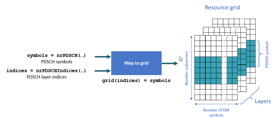
因为此示例在将 PDSCH 符号映射到资源网格之前对这些符号应用 MIMO 预编码,所以 MIMO 预编码的 PDSCH 符号指的是天线而不是层。要将层索引转换为天线索引,请使用 nrExtractResources 函数。下图显示了将 MIMO 预编码符号映射到与发射天线数一样多的资源网格的过程。
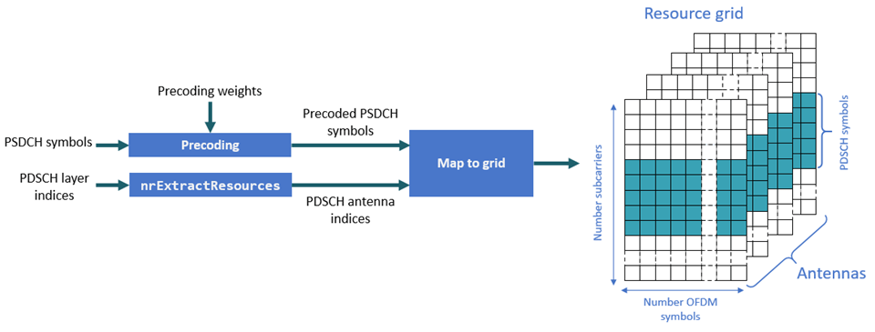
    [~,pdschAntIndices] = nrExtractResources(pdschIndices,pdschGrid);
    pdschGrid(pdschAntIndices) = pdschSymbolsPrecoded;
对 DM-RS 符号进行 MIMO 预编码并将其映射到资源网格。与 PDSCH 索引类似,DM-RS 索引指的是层。要将这些层索引转换为天线索引,请再次使用 nrExtractResources 函数。
    % PDSCH DM-RS precoding and mapping
    for p = 1:size(dmrsSymbols,2)
        [~,dmrsAntIndices] = nrExtractResources(dmrsIndices(:,p),pdschGrid);
        pdschGrid(dmrsAntIndices) = pdschGrid(dmrsAntIndices) + dmrsSymbols(:,p)*precodingWeights(p,:);
    end
OFDM 调制
对资源网格进行 OFDM 调制。
[txWaveform,waveformInfo] = nrOFDMModulate(carrier,pdschGrid);
传播信道
对于具有 N 个样本的输入,传播信道会生成 N 个输出样本。不过,包含 N 个输出样本的块包括信道滤波器瞬态(K 个样本)。因为同步阶段会消除此初始瞬态,所以,如果信道输出中的一个时隙有 N 个样本,则在同步后会剩余 N-K 个样本。N-K 个样本不足以解码一个时隙的数据。部分时隙样本位于信道滤波器延迟线中,尚未清空。要从信道滤波器中清出所有相关样本,请用零填充输入信号。信道滤波器导致的最大延迟会影响填充的大小。填充考虑了所有多径分量导致的延迟和信道滤波器实现延迟。下图显示了在波形进入信道之前填充零的必要性。

请用足够的零填充输入信号,以确保从信道滤波器中清出生成的信号。
    chInfo = info(channel);
    maxChDelay = chInfo.MaximumChannelDelay;
    txWaveform = [txWaveform; zeros(maxChDelay,size(txWaveform,2))];
请通过信道发送信号并添加噪声。只有启用了完美的信道估计时,输出 OFDM 信道响应 ofdmChannelResponse 和定时偏移 timingOffset 才适用。
    [rxWaveform,ofdmChannelResponse,timingOffset] = channel(txWaveform,carrier);
    [noise,nVar] = generateAWGN(SNRdB,nRxAnts,waveformInfo.Nfft,size(rxWaveform));
    rxWaveform = rxWaveform + noise;
定时同步
您可以执行完美同步或实际同步。
完美同步假设掌握了信道知识。当信道响应输出类型设置为
'ofdm-response'时,信道会直接返回此信息。实际同步则是在时域中将接收到的信号与 PDSCH DM-RS 符号互相关 (
nrTimingEstimate)。在某些不利情况下,由于衰落或噪声,这种互相关可能很弱,从而导致错误的定时偏移。函数hSkipWeakTimingOffset会检查互相关mag的程度。如果互相关不强,此函数会忽略当前的定时估计,而改用以前的估计 (offset)。
执行完美或实际定时估计和同步。
    if perfectEstimation
        % Perfect timing estimation is provided by the channel
        offset = timingOffset;
    else
        [t,mag] = nrTimingEstimate(carrier,rxWaveform,dmrsIndices,dmrsSymbols);
        offset = hSkipWeakTimingOffset(offset,t,mag);
    end
    rxWaveform = rxWaveform(1+offset:end,:);
OFDM 解调
对同步的信号进行 OFDM 解调。
rxGrid = nrOFDMDemodulate(carrier,rxWaveform);
信道估计
信道估计可用来表示每个资源元素 (RE) 的信道效应。均衡器使用此信息来补偿信道导致的失真。
您可以执行完美信道估计或实际信道估计。
完美信道估计假设掌握了信道知识。当信道响应输出类型设置为
'ofdm-response'时,信道会直接返回此信息。实际信道估计则使用 PDSCH DM-RS 来估计信道条件,并使用噪声平均和插值方法来获取时隙中所有 RE 的估计。因为 DM-RS 是按层指定的,所以得到的实际信道估计表示发射层与接收天线之间的信道条件。实际信道估计包括 MIMO 预编码操作的效应。
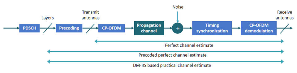
下图显示了下行链路处理链中的信道估计的参考点。
执行完美或实际信道估计。
    if perfectEstimation
        % Perfect channel estimation between transmit and receive antennas
        % provided by the channel
        estChGridAnts = ofdmChannelResponse;

        % Use the precalculated noise variance as the perfect noise
        % estimate
        noiseEst = nVar;

        % Get precoding matrix for next slot
        newPrecodingWeight = getPrecodingMatrix(pdsch.PRBSet,pdsch.NumLayers,estChGridAnts);

        % Apply precoding to estChGridAnts. The resulting estimate is for
        % the channel estimate between layers and receive antennas.
        estChGridLayers = precodeChannelEstimate(estChGridAnts,precodingWeights.');
    else
        % Perform practical channel estimation between layers and receive
        % antennas.
        [estChGridLayers,noiseEst] = nrChannelEstimate(carrier,rxGrid,dmrsIndices,dmrsSymbols,'CDMLengths',pdsch.DMRS.CDMLengths);

        % Remove precoding from estChannelGrid before precoding
        % matrix calculation
        estChGridAnts = precodeChannelEstimate(estChGridLayers,conj(precodingWeights));

        % Get precoding matrix for next slot
        newPrecodingWeight = getPrecodingMatrix(pdsch.PRBSet,pdsch.NumLayers,estChGridAnts);
    end
绘制第一层与第一个接收天线之间的信道估计。
    mesh(abs(estChGridLayers(:,:,1,1)));
    title('Channel Estimate');
    xlabel('OFDM Symbol');
    ylabel("Subcarrier");
    zlabel("Magnitude");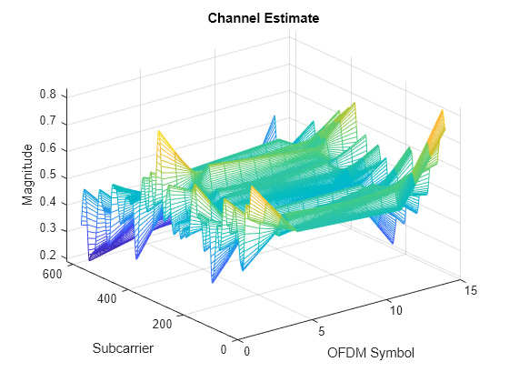
此时,您可以使用信道估计来获取下一个时隙中用于发射的预编码矩阵。因为此示例假设了掌握了发射机端的信道知识,所以您不需要计算接收机端的预编码矩阵。有关如何基于接收机端的信道估计来计算用于数据传输的预编码矩阵的示例,请参阅 NR PDSCH 吞吐量。
均衡
均衡器使用信道估计来补偿信道导致的失真。
从接收到的网格和关联的信道估计中提取 PDSCH 符号。csi 输出中包含每个均衡的 PDSCH 符号的信道状态信息 (CSI)。CSI 用于度量每个 PDSCH 符号的信道条件。在 PDSCH 解码后,使用 CSI 对解码的软比特进行加权,这可以有效地提高信道条件较好的符号的重要性。
    [pdschRx,pdschHest] = nrExtractResources(pdschIndices,rxGrid,estChGridLayers);
    [pdschEq,csi] = nrEqualizeMMSE(pdschRx,pdschHest,noiseEst);
绘制均衡的信号的星座图。绘图包括所有层的星座图。
    constPlot.ChannelNames = "Layer "+(pdsch.NumLayers:-1:1);
    constPlot.ShowLegend = true;
    % Constellation for the first layer has a higher SNR than that for the
    % last layer. Flip the layers so that the constellations do not mask
    % each other.
    constPlot(fliplr(pdschEq));
![]()
PDSCH 解码
对均衡的 PDSCH 符号进行解码,并获取软比特码字。
[dlschLLRs,rxSymbols] = nrPDSCHDecode(carrier,pdsch,pdschEq,noiseEst);
根据 CSI 对软比特或对数似然比 (LLR) 进行定标。此定标会向 RE 中信道条件较好的符号应用较大的权重。
    % Scale LLRs by CSI
    csi = nrLayerDemap(csi);                                    % CSI layer demapping
    for cwIdx = 1:pdsch.NumCodewords
        Qm = length(dlschLLRs{cwIdx})/length(rxSymbols{cwIdx}); % Bits per symbol
        csi{cwIdx} = repmat(csi{cwIdx}.',Qm,1);                 % Expand by each bit per symbol
        dlschLLRs{cwIdx} = dlschLLRs{cwIdx} .* csi{cwIdx}(:);   % Scale
    end
DL-SCH 解码
对 LLR 进行解码并检查是否存在错误。
    decodeDLSCH.TransportBlockLength = trBlkSizes;
    [decbits,blkerr] = decodeDLSCH(dlschLLRs,pdsch.Modulation,pdsch.NumLayers, ...
        harqEntity.RedundancyVersion,harqEntity.HARQProcessID);
HARQ 进程更新
使用得到的块错误状态更新当前的 HARQ 进程,然后推进到下一个进程。此步骤会更新与 HARQ 实体中的活动 HARQ 进程相关的信息。
statusReport = updateAndAdvance(harqEntity,blkerr,trBlkSizes,pdschInfo.G);
汇总当前时隙的 HARQ 和解码信息。
    disp("Slot "+(nSlot)+". "+statusReport);
end % for nSlot = 0:totalNoSlots
Slot 0. HARQ Proc 0: CW0: Initial transmission passed  (TBS=24072,RV=0,CR=0.482212).
Slot 1. HARQ Proc 1: CW0: Initial transmission passed  (TBS=24072,RV=0,CR=0.482212).
Slot 2. HARQ Proc 2: CW0: Initial transmission passed  (TBS=24072,RV=0,CR=0.482212).
Slot 3. HARQ Proc 3: CW0: Initial transmission passed  (TBS=24072,RV=0,CR=0.482212).
Slot 4. HARQ Proc 4: CW0: Initial transmission passed  (TBS=24072,RV=0,CR=0.482212).
Slot 5. HARQ Proc 5: CW0: Initial transmission passed  (TBS=24072,RV=0,CR=0.482212).
Slot 6. HARQ Proc 6: CW0: Initial transmission passed  (TBS=24072,RV=0,CR=0.482212).
Slot 7. HARQ Proc 7: CW0: Initial transmission passed  (TBS=24072,RV=0,CR=0.482212).
Slot 8. HARQ Proc 8: CW0: Initial transmission passed  (TBS=24072,RV=0,CR=0.482212).
Slot 9. HARQ Proc 9: CW0: Initial transmission passed  (TBS=24072,RV=0,CR=0.482212).
Slot 10. HARQ Proc 10: CW0: Initial transmission passed  (TBS=24072,RV=0,CR=0.482212).
Slot 11. HARQ Proc 11: CW0: Initial transmission passed  (TBS=24072,RV=0,CR=0.482212).
Slot 12. HARQ Proc 12: CW0: Initial transmission passed  (TBS=24072,RV=0,CR=0.482212).
Slot 13. HARQ Proc 13: CW0: Initial transmission passed  (TBS=24072,RV=0,CR=0.482212).
Slot 14. HARQ Proc 14: CW0: Initial transmission passed  (TBS=24072,RV=0,CR=0.482212).
Slot 15. HARQ Proc 15: CW0: Initial transmission passed  (TBS=24072,RV=0,CR=0.482212).
Slot 16. HARQ Proc 0: CW0: Initial transmission passed  (TBS=24072,RV=0,CR=0.482212).
Slot 17. HARQ Proc 1: CW0: Initial transmission passed  (TBS=24072,RV=0,CR=0.482212).
Slot 18. HARQ Proc 2: CW0: Initial transmission passed  (TBS=24072,RV=0,CR=0.482212).
Slot 19. HARQ Proc 3: CW0: Initial transmission passed  (TBS=24072,RV=0,CR=0.482212).
局部函数
function [noise,nVar] = generateAWGN(SNRdB,nRxAnts,Nfft,sizeRxWaveform)
% Generate AWGN for a given value of SNR in dB (SNRDB), which is the
% receiver SNR per RE and antenna, assuming the channel does
% not affect the power of the signal. NRXANTS is the number of receive
% antennas. NFFT is the FFT size used in OFDM demodulation. SIZERXWAVEFORM
% is the size of the receive waveform used to calculate the size of the
% noise matrix.

    % Normalize noise power by the IFFT size used in OFDM modulation, as
    % the OFDM modulator applies this normalization to the transmitted
    % waveform. Also normalize by the number of receive antennas, as the
    % channel model applies this normalization to the received waveform by
    % default. The SNR is defined per RE for each receive antenna (TS
    % 38.101-4).
    SNR = 10^(SNRdB/10); % Calculate linear noise gain
    N0 = 1/sqrt(nRxAnts*double(Nfft)*SNR);
    noise = N0*randn(sizeRxWaveform,"like",1i);
    nVar = N0^2*double(Nfft);
end

function wtx = getPrecodingMatrix(PRBSet,NLayers,hestGrid)
% Calculate precoding matrix given an allocation and a channel estimate

    % Allocated subcarrier indices
    allocSc = (1:12)' + 12*PRBSet(:).';
    allocSc = allocSc(:);

    % Average channel estimate
    [~,~,R,P] = size(hestGrid);
    estAllocGrid = hestGrid(allocSc,:,:,:);
    Hest = permute(mean(reshape(estAllocGrid,[],R,P)),[2 3 1]);

    % SVD decomposition
    [~,~,V] = svd(Hest);

    wtx = V(:,1:NLayers).';
    wtx = wtx/sqrt(NLayers); % Normalize by NLayers
end

function estChannelGrid = getInitialChannelEstimate(channel,carrier)
% Obtain an initial channel estimate for calculating the precoding matrix.
% This function assumes a perfect channel estimate

    % Clone of the channel
    chClone = channel.clone();
    chClone.release();

    % No filtering needed to get channel path gains
    chClone.ChannelFiltering = false;

    % Set channel response output type to calculate perfect channel
    % estimation
    chClone.ChannelResponseOutput = 'ofdm-response';

    % Get perfect channel estimate directly from the channel
    estChannelGrid = chClone(carrier);
end

function refPoints = getConstellationRefPoints(mod)
% Calculate the reference constellation points for a given modulation
% scheme.
    switch mod
        case "QPSK"
            nPts = 4;
        case "16QAM"
            nPts = 16;
        case "64QAM"
            nPts = 64;
        case "256QAM"
            nPts = 256;
    end
    binaryValues = int2bit(0:nPts-1,log2(nPts));
    refPoints = nrSymbolModulate(binaryValues(:),mod);
end

function estChannelGrid = precodeChannelEstimate(estChannelGrid,W)
% Apply precoding matrix W to the last dimension of the channel estimate.

    % Linearize 4-D matrix and reshape after multiplication
    K = size(estChannelGrid,1);
    L = size(estChannelGrid,2);
    R = size(estChannelGrid,3);
    estChannelGrid = reshape(estChannelGrid,K*L*R,[]);
    estChannelGrid = estChannelGrid*W;
    estChannelGrid = reshape(estChannelGrid,K,L,R,[]);

end