NR Cell Performance Evaluation with MIMO Using Wireless Network Modeler App
This example uses the Wireless Network Modeler app to model a 5G New Radio (NR) cell with a multiple-input multiple-output (MIMO) antenna configuration operating in frequency division duplex (FDD) mode, and to evaluate the network performance. The example uses multi-port channel state information reference signals (CSI-RS) to measure downlink (DL) channel characteristics. To measure uplink (UL) channel characteristics, the example uses the sounding reference signal (SRS). For more information about key MIMO aspects such as spatial multiplexing, precoding, channel measurement, and reporting, see NR Cell Performance Evaluation with MIMO.
First, you must create an NR cell in the Wireless Network Modeler app.
Create NR Network
Create an NR network consisting of a 5G base station (gNB) and four user equipment (UE) nodes by following these steps.
Open the Wireless Network Modeler app.
MATLAB Toolstrip: On the Apps tab, under Wireless Communications, click the app icon

MATLAB Command Prompt: Enter
wirelessNetworkModeler
On the app toolstrip, click New Session and select 5G Network.
In the New 5G Network dialog box, set Scenario Type to
Rural macro.In the Nodes Placement section, set Number of gNBs to
1, UE Placement toEach cell, and Number of UEs to4.Clear Enable full buffer application data traffic.
Click Create Network.

Select PHY Model
To select the physical layer (PHY) model, in the Property Editor: Network, set the
PHY Model parameter. Note that, by default, the app sets the
PHY Model (Physical layer mode) to Abstract PHY.
The example retains this default setting. Alternatively, you can set the PHY
Model to Full PHY.
Configure NR Nodes
Configure the gNB and UE nodes by following these steps.
In the Network Browser pane, select gNB1. In the Property Editor: Node pane for gNB1, set X (m), Y (m), and Z (m) coordinates of the Position parameter to 0, 0, and 30 respectively.
In the Property Editor: Node pane for gNB1, in the Node Configuration section, set these parameters:
Receive Gain (dB) —
11Number of Transmit Antennas —
16Number of Receive Antenna —
16Carrier Frequency (Hz) —
2.6e+09Channel Bandwidth (MHz) —
5Subcarrier Spacing (kHz) —
15Duplex Mode —
FDDSRS Periodicity (slots) —
40
In the Property Editor: Node pane for gNB1, in the Scheduler Configuration section, set DL CSI Measurement Signal to
CSI-RS.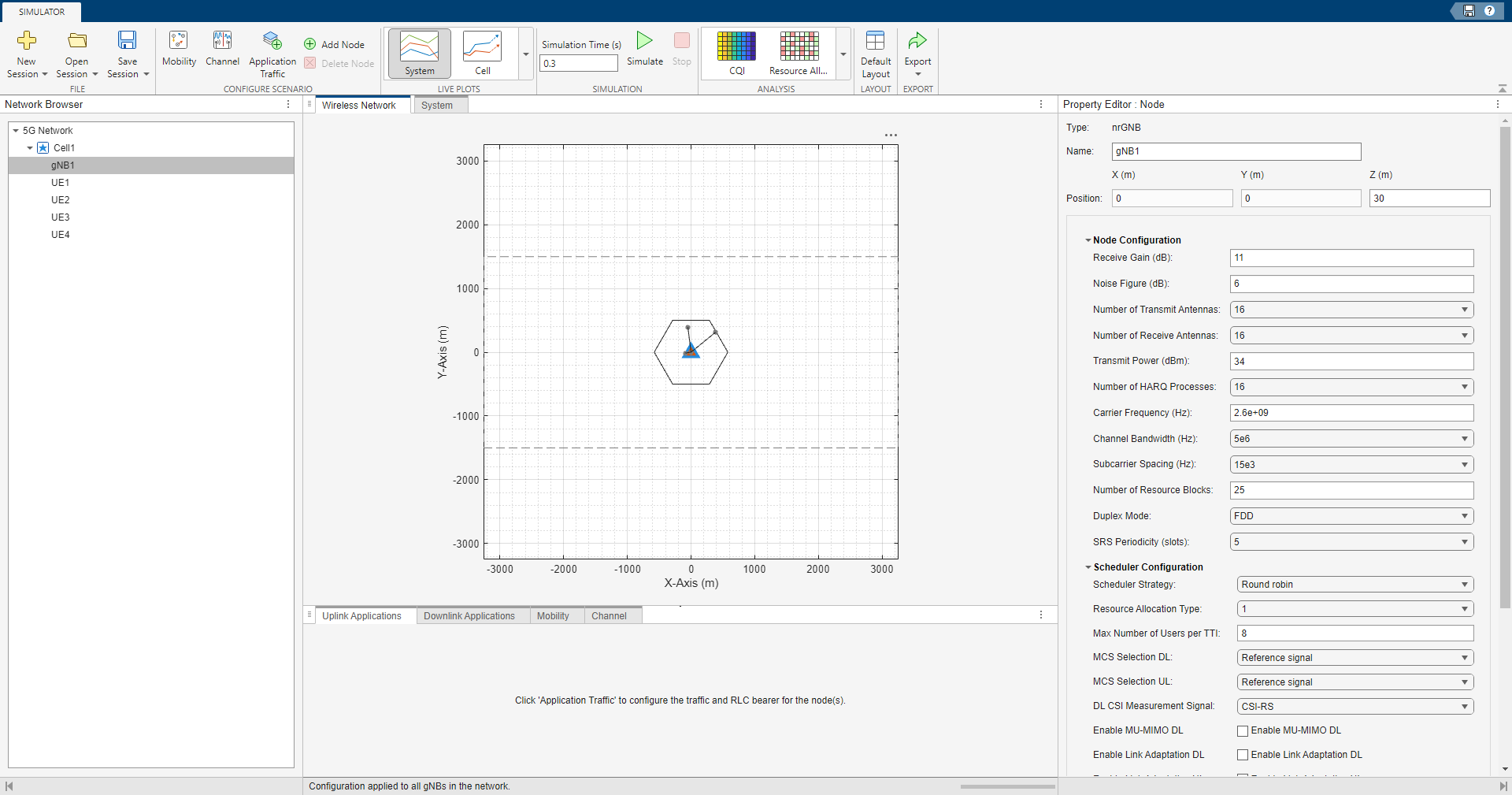
Click Apply.
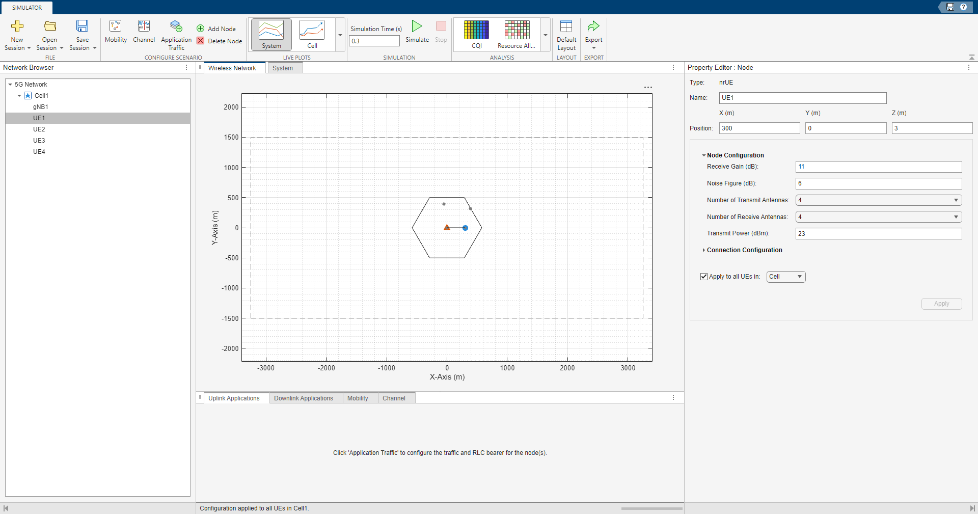
In the Network Browser pane, select UE1. In the Property Editor: Node pane for UE1, set the X (m), Y (m), and Z(m) coordinates of the Position parameter to
300,0, and3, respectively.In the Property Editor: Node pane for UE1, in the Node Configuration section, set these parameters:
Receive Gain (dB) —
11Number of Transmit Antennas —
4Number of Receive Antennas —
4
In the Property Editor: Node pane for UE1, in the Connection Configuration section, set CSI Report Periodicity (slots) to
80. Then, select Apply to all UEs in, and set the parameter to Cell. Click Apply.In the Network Browser pane, select each of the remaining UEs and, in the Property Editor: Node pane, specify these Position values for each:
UE2 — Set X (m) to
700, Y (m) to0, and Z (m) to3.UE3 — Set X (m) to
1200, Y (m) to0, and Z (m) to3.UE4 — Set X (m) to
3000, Y (m) to0, and Z (m) to3.
Establish RLC Bearer Between gNB and Each UE Nodes
Establish a radio link control (RLC) bearer between the gNB and each UE node by following these steps:
In the Configure Scenario section of the toolstrip, select Application Traffic.
In the Customize section of the toolstrip, select RLC Templates.
In the Custom RLC Templates dialog box, set SN field length (bits) to
6and Bucket size duration (ms) to10. Click OK.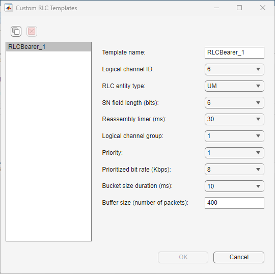
Add Application Traffic
Follow these steps to add the application traffic.
In the Customize section of the app toolstrip, click Application Templates.
In the Custom Application Templates dialog box, in the left pane, select
On-Offand click to create a custom On-Off traffic template.
For the custom On-Off traffic template, specify Template Name as
Custom_OnOff_1. Set On Time Type and Off Time Type toFixed. Set Data Rate (Kbps) to40000. Click OK.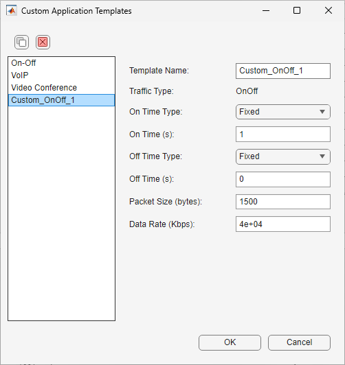
In the Select uplink node pair(s) pane, select All UEs in the 5G Network. In the Select and apply templates pane, set Application Template to
Custom_OnOff_1and RLC Template toRLC_Bearer_1, and click Apply.Select Downlink Application from the toolstrip. In the Select downlink node pair(s) pane, select All gNBs in 5G Network. In the Select and apply templates pane, set Application Template to
Custom_OnOff_1and RLC Template toRLC_Bearer_1, and click Apply.On the app toolstrip, click Accept.
Configure Custom Channel
Configure a custom channel by following these steps:
In the Configure Scenario section of the app toolstrip, select Channel.
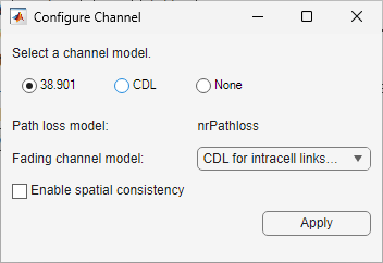
In the Configure Channel dialog box, set Select a channel model to
38.901.Click Apply.
Simulate and Analyze Network Performance
Analyze the cell-level performance of the network in terms of UL throughput, DL
throughput, UL block error rate (BLER), and DL BLER, go to the app toolstrip. From the
Live Plots section of the app toolstrip, select
Cell. Then, in the Simulation section, set
Simulation Time (s) to 1 and click
Simulate.
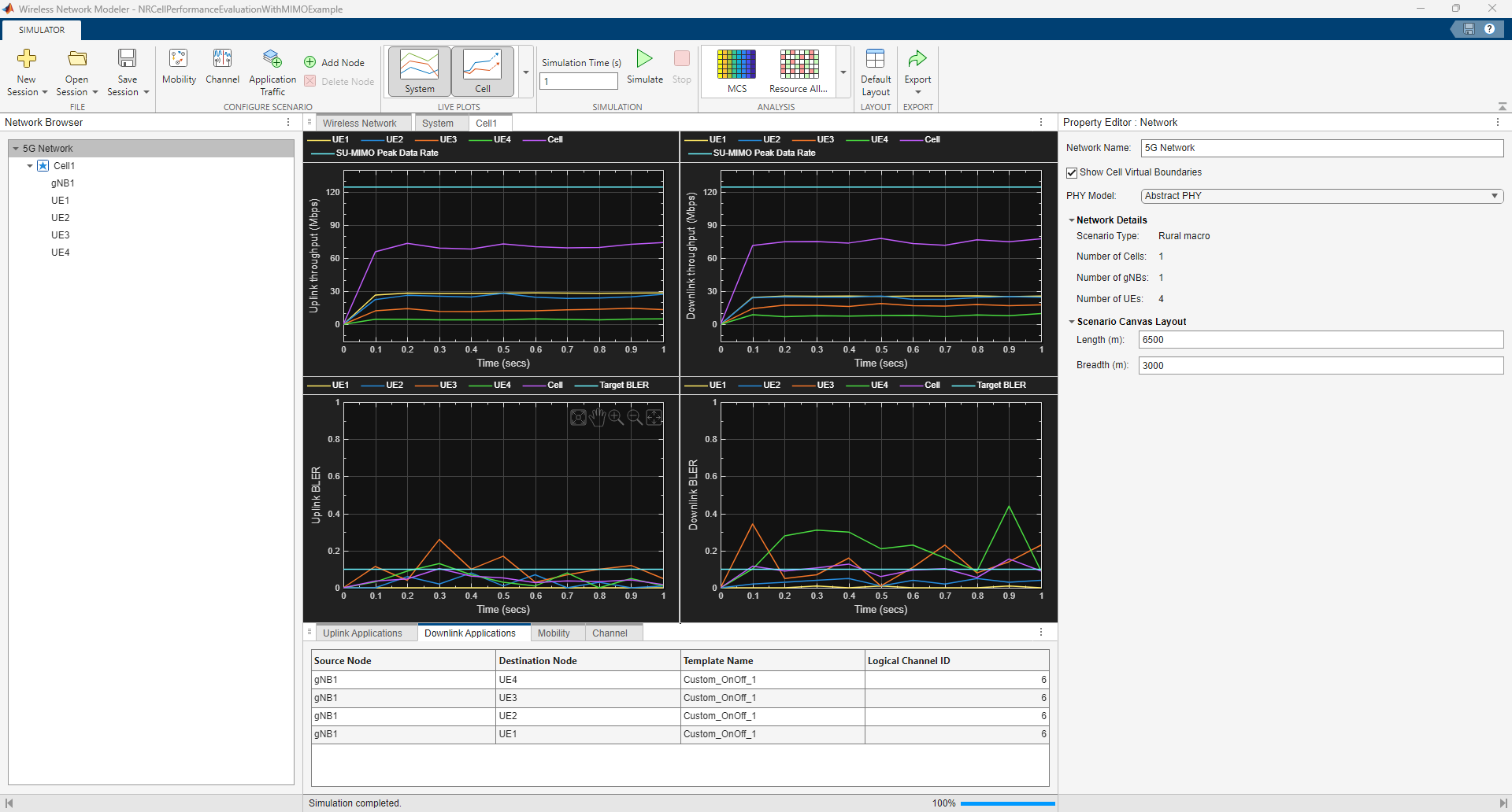
To obtain the values of he key performance indicators (KPIs), click Export on the toolstrip and select Export Results and Logs. This table summarizes the KPIs for the UL and DL directions observed in the figure.
| KPI | UL | DL |
|---|---|---|
| Peak throughput | 124.42 | 124.42 |
| Achieved cell throughput (Mbps) | 70.57 | 74.72 |
| Achieved throughput per UE (Mbps) |
|
|
| Peak spectral efficiency (bits/s/Hz) | 24.88 | 24.88 |
| Achieved spectral efficiency (bits/s/Hz) | 14.11 | 14.94 |
| Block error rate per UE |
|
|
Further Exploration
Try running the example with SRS-based DL single-user MIMO, and analyze its impact on the KPIs.
See Also
Apps
- Wireless Network Modeler (Wireless Network Toolbox)