使用 CSI-RS 执行 NR 信道估计
R2026b此示例说明如何为给定载波和 CSI-RS 资源配置生成信道状态信息参考信号 (CSI-RS) 符号和索引,如 TS 38.211 第 7.4.1.5 节中所定义。该示例说明如何将生成的符号映射到载波资源网格,在接收机端执行信道估计,并将估计信道与实际信道进行比较。
简介
CSI-RS 是下行链路专用 (DL) 参考信号。NR 标准定义了零功率 (ZP) 和非零功率 (NZP) CSI-RS。
用户设备 (UE) 进程利用 NZP-CSI-RS 完成以下操作:
测量 L1 参考信号接收功率 (RSRP) 以进行移动性和波束管理
获取 DL CSI
测量干扰
跟踪时间和频率
ZP-CSI-RS 用于获取 DL CSI 和测量干扰。它还会掩蔽某些资源元素 (RE),使其无法用于 PDSCH 传输。顾名思义,ZP(零功率)表示在这些 RE 中不传输任何内容。
此示例说明如何使用 CSI-RS 执行信道估计,这是获取 CSI 的基础。
初始化配置对象
创建一个载波配置对象,表示一个子载波间隔为 15 kHz 的 5 MHz 载波。
carrier = nrCarrierConfig;
carrier.NSizeGrid = 25;
carrier.SubcarrierSpacing = 15;
carrier.NSlot = 1;
carrier.NFrame = 0
carrier =
  nrCarrierConfig with properties:

                NCellID: 1
      SubcarrierSpacing: 15
           CyclicPrefix: 'normal'
              NSizeGrid: 25
             NStartGrid: 0
                  NSlot: 1
                 NFrame: 0
    IntraCellGuardBands: [0×2 double]

   Read-only properties:
         SymbolsPerSlot: 14
       SlotsPerSubframe: 1
          SlotsPerFrame: 10
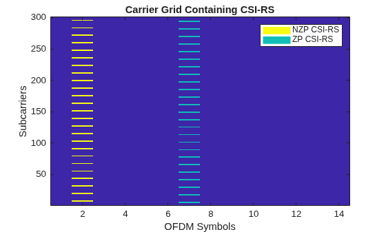
创建一个 CSI-RS 配置对象,表示两个 CSI-RS 资源:行号为 3 的 NZP 资源和行号为 5 的 ZP 资源。
csirs = nrCSIRSConfig;
csirs.CSIRSType = {'nzp','zp'};
csirs.CSIRSPeriod = {[5 1],[5 1]};
csirs.Density = {'one','one'};
csirs.RowNumber = [3 5];
csirs.SymbolLocations = {1,6};
csirs.SubcarrierLocations = {6,4};
csirs.NumRB = 25
csirs =
nrCSIRSConfig with properties:
CSIRSType: {'nzp' 'zp'}
CSIRSPeriod: {[5 1] [5 1]}
RowNumber: [3 5]
Density: {'one' 'one'}
SymbolLocations: {[1] [6]}
SubcarrierLocations: {[6] [4]}
NumRB: 25
RBOffset: 0
NID: 0
NumAggregatedResources: 1
Read-only properties:
NumCSIRSPorts: [2 4]
CDMType: {'FD-CDM2' 'FD-CDM2'}
考虑 CSI-RS 的功率缩放 (dB)。
powerCSIRS = 0;
disp(['CSI-RS power scaling: ' num2str(powerCSIRS) ' dB']);
CSI-RS power scaling: 0 dB
生成 CSI-RS 符号和索引
针对指定的载波和 CSI-RS 配置参数生成 CSI-RS 符号。应用功率缩放。
sym = nrCSIRS(carrier,csirs);
csirsSym = sym*db2mag(powerCSIRS);
变量 csirsSym 是一个包含 CSI-RS 符号的列向量。
针对指定的载波和 CSI-RS 配置参数生成 CSI-RS 索引。
csirsInd = nrCSIRSIndices(carrier,csirs);
变量 csirsInd 也是一个列向量,其大小与 csirsSym 相同。
当您同时配置 ZP 和 NZP 资源时,ZP 信号的生成优先于 NZP 信号的生成。
初始化载波网格
初始化一个时隙的载波资源网格。
ports = max(csirs.NumCSIRSPorts);   % Number of antenna ports
txGrid = nrResourceGrid(carrier,ports);
将 CSI-RS 符号映射到载波网格
执行资源元素映射。
txGrid(csirsInd) = csirsSym;
绘制 CSI-RS(包括 ZP 和 NZP)在网格中的位置。
plotGrid(size(txGrid),csirsInd,csirsSym);
执行 OFDM 调制
执行 OFDM 调制以生成时域波形。
[txWaveform,ofdmInfo] = nrOFDMModulate(carrier,txGrid);
通过信道传输时域波形并添加 AWGN 噪声
配置接收天线的数量。
R = 4;
配置信道。
channel = nrTDLChannel;
channel.NumTransmitAntennas = ports;
channel.NumReceiveAntennas = R;
channel.DelayProfile = 'TDL-C';
channel.MaximumDopplerShift = 10;
channel.DelaySpread = 1e-8;
设置信道的采样率。
waveformInfo = nrOFDMInfo(carrier);
channel.SampleRate = waveformInfo.SampleRate
channel =
  nrTDLChannel with properties:

                 DelayProfile: 'TDL-C'
                  DelaySpread: 1.0000e-08
          MaximumDopplerShift: 10
                   SampleRate: 7680000
           PathGainSampleRate: 'signal'
              MIMOCorrelation: 'Low'
                 Polarization: 'Co-Polar'
        TransmissionDirection: 'Downlink'
          NumTransmitAntennas: 4
           NumReceiveAntennas: 4
           NormalizePathGains: true
                  InitialTime: 0
                 NumSinusoids: 48
                 RandomStream: 'mt19937ar with seed'
                         Seed: 73
      NormalizeChannelOutputs: true
             ChannelFiltering: true
    TransmitAndReceiveSwapped: false
        ChannelResponseOutput: 'path-gains'
基于配置的信道,在发射波形后补零,以补偿信道延迟。
chInfo = info(channel);
maxChDelay = chInfo.MaximumChannelDelay;
txWaveform = [txWaveform; zeros(maxChDelay,size(txWaveform,2))];
通过信道传输波形。
[rxWaveform,pathGains] = channel(txWaveform);
要生成实际传播信道 H_actual,请执行完美信道估计。
pathFilters = getPathFilters(channel);
H_actual = nrPerfectChannelEstimate(carrier,pathGains,pathFilters);
向波形添加 AWGN 噪声。有关此示例使用的 SNR 定义的说明,请参阅SNR Definition Used in Link Simulations。
SNRdB = 50;           % in dB
SNR = 10^(SNRdB/10);  % Linear value
N0 = 1/sqrt(2.0*R*double(ofdmInfo.Nfft)*SNR); % Noise variance
rng(0);
noise = N0*complex(randn(size(rxWaveform)),randn(size(rxWaveform)));
rxWaveform = rxWaveform + noise;
使用 NZP-CSI-RS 执行定时同步。要估计定时偏移,请使用 nrTimingEstimate,并将 NZP-CSI-RS 作为参考。
% Disable ZP-CSI-RS resource, not going to be used for timing and channel
% estimation
csirs.CSIRSPeriod = {[5 1],'off'};
% Generate reference symbols and apply power scaling
refSym = db2mag(powerCSIRS)*nrCSIRS(carrier,csirs);
% Generate reference indices
refInd = nrCSIRSIndices(carrier,csirs);
offset = nrTimingEstimate(carrier,rxWaveform,refInd,refSym)
offset =
7
rxWaveform = rxWaveform(1+offset:end,:);
对接收的时域波形进行 OFDM 解调。
rxGrid = nrOFDMDemodulate(carrier,rxWaveform); % Of size K-by-L-by-R将估计信道与实际信道进行比较
使用 NZP-CSI-RS 执行实际信道估计。确保 CSI-RS 符号 csirsSym 具有相同的 CDM 类型。
cdmLen = [2 1]; % Corresponds to CDMType = 'FD-CDM2'
[H_est,nVar] = nrChannelEstimate(carrier,rxGrid,refInd,refSym,'CDMLengths',cdmLen);
disp(['Estimated noise variance = ' num2str(nVar)])
Estimated noise variance = 0.00011155
绘制第一个发射天线与第一个接收天线之间的估计信道和实际信道。
figure;

% Plot the estimated channel
subplot(1,2,1)
imagesc(abs(H_est(:,:,1,1)));
colorbar;
title('Estimated Channel')
axis xy;
xlabel('OFDM Symbols');
ylabel('Subcarriers');

% Plot the actual channel
subplot(1,2,2)
imagesc(abs(H_actual(:,:,1,1)));
colorbar;
title('Actual Channel')
axis xy;
xlabel('OFDM Symbols');
ylabel('Subcarriers');
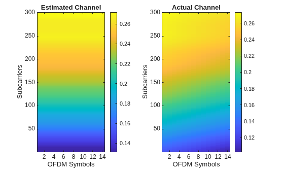
计算信道估计误差。
H_err = (H_est - H_actual(:,:,:,1:size(H_est,4)));
[minErr,maxErr] = bounds(abs(H_err),'all');
disp(['Absolute value of the channel estimation error is in the range of [' num2str(minErr) ', ' num2str(maxErr) ']'])
Absolute value of the channel estimation error is in the range of [2.4865e-05, 0.029678]
局部函数
function plotGrid(gridSize,csirsInd,csirsSym)
%    plotGrid(GRIDSIZE,CSIRSIND,CSIRSSYM) plots the carrier grid of size GRIDSIZE
%    by populating the grid with CSI-RS symbols using CSIRSIND and CSIRSSYM.

    figure()
    cmap = colormap(gcf);
    chpval = {20,2};
    chpscale = 0.25*length(cmap); % Scaling factor

    tempSym = csirsSym;
    tempSym(tempSym ~= 0) = chpval{1}; % Replacing non-zero-power symbols
    tempSym(tempSym == 0) = chpval{2}; % Replacing zero-power symbols
    tempGrid = complex(zeros(gridSize));
    tempGrid(csirsInd) = tempSym;

    image(chpscale*tempGrid(:,:,1)); % Multiplied with scaling factor for better visualization
    axis xy;
    names = {'NZP CSI-RS','ZP CSI-RS'};
    clevels = chpscale*[chpval{:}];
    N = length(clevels);
    L = line(ones(N),ones(N),'LineWidth',8); % Generate lines
    % Index the color map and associate the selected colors with the lines
    set(L,{'color'},mat2cell(cmap( min(1+clevels,length(cmap) ),:),ones(1,N),3)); % Set the colors according to cmap
    % Create legend
    legend(names{:});

    title('Carrier Grid Containing CSI-RS')
    xlabel('OFDM Symbols');
    ylabel('Subcarriers');
end
参考
[1] 3GPP TS 38.211. “NR; Physical channels and modulation.” 3rd Generation Partnership Project; Technical Specification Group Radio Access Network.

