Electrical Component Analysis for Hybrid and Electric Aircraft
This example illustrates how to use modeling for rapid exploration of design space in the hybrid and electric aircraft area and compare the results to design criteria. This process can reduce the number of design iterations and ensure that the final design meets system-level requirements.
Hybrid and electric aircraft are areas of aggressive development in the aerospace industry. To accelerate the process of choosing between hybrid and pure electric power systems, select power network architectures, and size electrical components, consider using simulation with MathWorks® products.
Using preconfigured simulation configurations, this example shows the tradeoffs between battery sizes for a pure electric or hybrid electric power system, with and without payloads. It includes the Pipistrel Alpha Electro and NASA X-57 Maxwell aircraft. Implemented as a project, the example provides various shortcuts that you can use to experiment with simulation.
Model Components
The Aircraft block specifies the aircraft compared in the project:
Pipistrel Alpha Electro[1], a preconfigured model of the world's first two-seat pure electric training aircraft.
NASA X-57 Maxwell[2], a preconfigured model of the NASA X-57 Maxwell aircraft, an experimental electric aircraft.
Custom, an aircraft that you can model according to your specifications.
In the Aircraft block, each aircraft is modeled as a 4th Order Point Mass (Longitudinal) in flight, with the required thrust output as a load on the motor. This abstract model assumes that the pilot takes the actions necessary to follow the mission.
You can specify several aerodynamic characteristics for the selected aircraft, including empty and maximum mass, wing area and lift curve values, a drag coefficient, and target speeds for the climb, cruise, and descent portions of the mission. The block uses these values, along with the mission altitudes, to create lookup tables for angle of attack (alpha) and thrust, given atmospheric density, target speed, and flight profile angle (gamma). At every point along the flight, the lookup tables return alpha and thrust for input into the 4th-order Point Mass block, which calculates the accelerations. By holding alpha and thrust at the calculated, steady-state values, the actual speed quickly reaches the desired speed. The Aircraft block also defines the climb and descent rates for the mission.
The Mission Profile block sets the airport and cruise altitudes and the total flight distance. If entered values are not feasible, such as a distance too short for the aircraft to climb to and descend from the requested cruise altitude, then the values are adjusted, and a message describes the change. To see how far the aircraft can fly until it runs out of battery power, enter a long total flight distance.
The Environment block calculates the air density at the chosen altitudes using the COESA Atmosphere Model.
Run the Model with Default Settings
By default, the Aircraft block is configured for the Pipistrel Alpha Electro aircraft. To see the performance of this aircraft with default settings, run the model using the "Single Run" project shortcut. The Pipistrel is run with no payload.
Two figures display showing the battery states, current, and power levels during the flight. Two scope windows show the mission progress (altitude and airspeed), power output, and energy used. Note, the battery runs out of capacity (reaches 20 amp-hours) before the entire mission is completed.
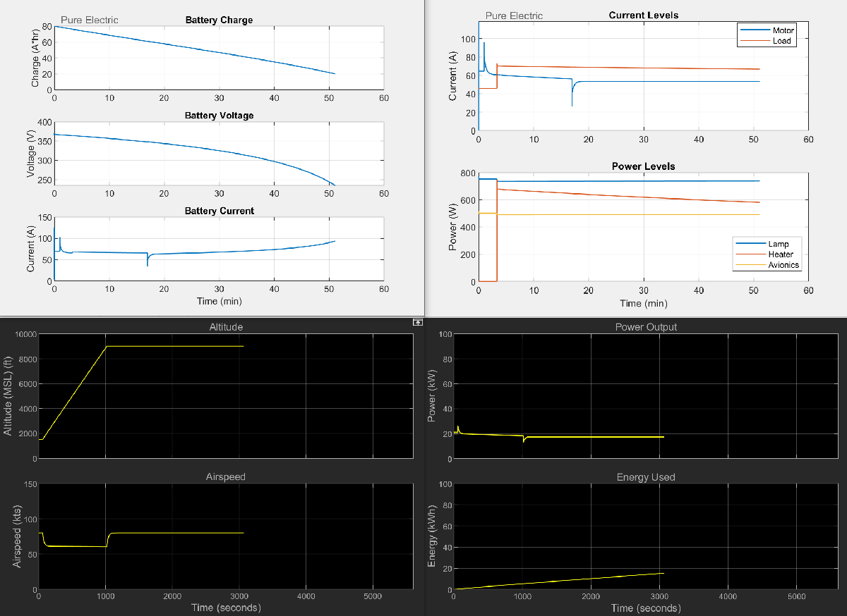
To capture the data created by a simulation, the example uses the Simscape Data Logging (Simscape) capability. The various simulation cases provided by the project shortcuts run scripts that run the desired cases and then extract the results from the Simscape log to create the figures. For aircraft with more than one electric motor, the total required torque calculated by the Aircraft subsystem is divided by the number of motors before being passed to the Power subsystem. The criteria to stop the simulation, batteryCapacityMin, is adjusted up from 20 amp-hours accordingly.
Run the Model with Cruise at 3000 Feet
The Pipistrel is designed as a primary flight trainer. The default mission configured for the model might not be the typical mission for the Pipistrel. Modify the mission to cruise at 3000 instead of 9000 feet, and then make a single run to see the effect of this change (duration decreases).
Run the Model with a Payload
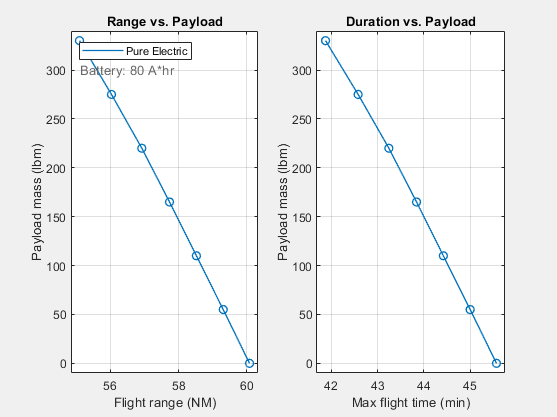
To run the Pipistrel with a 165 pound payload, use the "Set Payload Mass" shortcut, then run the model again. To see the effect of a range of payload values, use the "Sweep Payload Mass" shortcut. This shortcut varies the payload from 0 to 330 pounds. The sweeps produce different figures, showing the flight time and range for the swept parameter. Each marker represents one simulation. Hover your mouse over a marker to see its payload mass ("X") and flight range or duration ("Y") values.
Run the Model with Various Battery Sizes
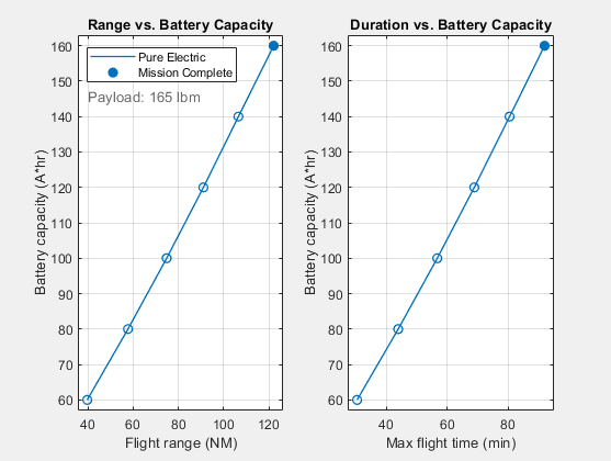
To see how the flight range is affected by the battery size, use the "Sweep Battery Size" shortcut. The shortcut varies the capacity from 60 to 160 amp-hours (or 100 to 200 amp-hours if the X-57 is selected). The example assumes the battery mass to be linearly proportional to its capacity, so increasing its capacity increases its mass as well. If the payload is set large enough (over 183 pounds for the Pipistrel), this increase in battery mass can cause the largest battery in the sweep to put the aircraft over its maximum mass value (e.g. 1212 pounds for the Pipistrel). The total_mass variable in the base workspace stores the total mass of each case in the sweep. If the battery capacity is enough to complete the mission, a filled marker indicates this. Note that pure electric aircraft, such as the Pipistrel, have no fuel burn, resulting in no change in mass throughout a flight.
Run the Model with Maximum Payload
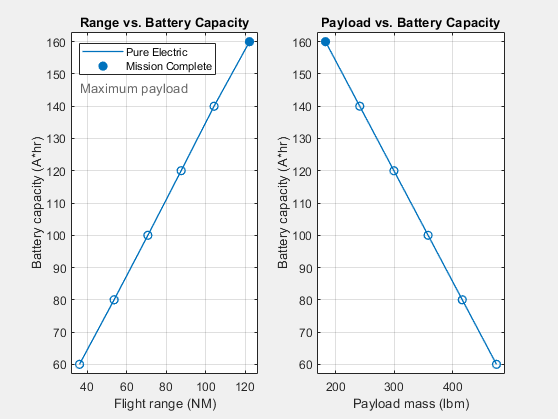
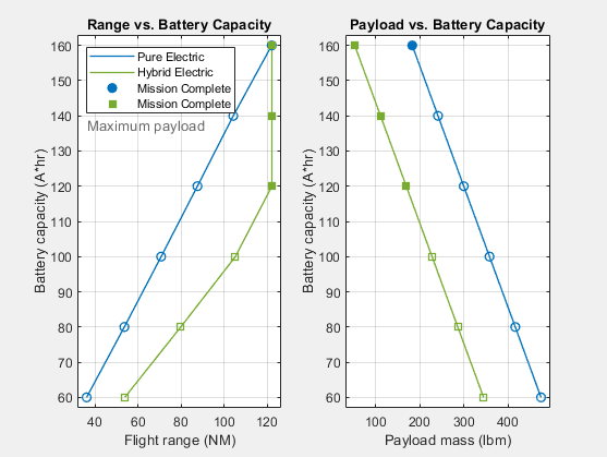
The battery capacity sweep in "Run the Model with Various Battery Sizes" yields the flight range for a fixed payload. To find the flight range for the maximum payload, use the "Sweep Range at Max Payload" shortcut. This sweeps the battery capacity with the payload set such that the total mass equals the maximum mass in every case (unless payload becomes negative, in which case payload is set to zero and the model goes overweight). From these results, you can choose the maximum battery size for a given payload requirement.
Run the Model with Various Battery and Payload Sizes
To simultaneously see the flight range distance dependence on both battery size and payload mass, use the "Sweep Battery & Payload" shortcut, which produces a contour plot. Areas where the aircraft is over the maximum weight are denoted with a red and white "Overweight" overlay.

Run the Model with the Hybrid Electric Option
Since battery power density is much less than that of aviation fuel, pure electric aircraft have less distance range than their fuel-powered counterparts. To bridge this gap, consider a hybrid electric power system. To recharge the batteries, the hybrid power subsystem variant in this example adds a 130 pound, 50 kW, two-stroke piston engine and generator to the pure electric power subsystem components.
To try a hybrid power system, perform one of these workflows:
Change Power Subsystem Variant and Run the Battery Range Sweep
1. Use the "Hybrid Electric" shortcut. This shortcut changes the Power subsystem variant.
2. To repeat the sweep previously done for pure electric power, use "Sweep Range at Max Payload".

In this case the larger battery sizes are capable of longer missions than what is currently defined (120 NM). Try entering a longer total flight distance (e.g. 200 NM) in the Mission Profile and then rerun this sweep.
Run the Battery Range Sweep for Both Power Variants
1. Use the "Hybrid/Electric Range Comparison" shortcut to run the sweep for both power variants.
2. Compare the results in a single figure. The results show that a hybrid power system can improve range, but at the expense of payload.
Explore How the Mission Affects Range and Endurance
To explore how the mission affects the range and endurance, select the Custom aircraft model in the Aircraft block. The default configuration values for this aircraft are the same as for the Pipistrel, with the exception of the speeds. Adjust the speeds and mission altitudes as desired, then run and compare the results to those for the Pipistrel with default settings.
If the custom aircraft being evaluated is significantly different from the Pipistrel, then accordingly adjust the CustomAircraft values in the "asbHybridAircraftDefaults.m" file.
Additional Model Details
Power Subsystem
The power subsystem is modeled with two variant models: Pure Electric and Hybrid Electric, controlled by the variable POWER_MODE in the base workspace.
The Pure Electric model includes a battery, high- and low-voltage DC networks, and a mechanical model of the aircraft. The mechanical model acts as a load on the high-voltage DC network. The low-voltage DC network includes a set of loads that turn on and off during the flight mission.
The series Hybrid Electric model contains all the components in the Pure Electric model, plus a 50 kW engine, a generator, and fuel. The Generic Engine (Simscape Driveline) drives a generator that supplements the power available from the battery. The generator recharges the battery during flight. The mass of the fuel consumed by the engine is included in the simulation. The low-voltage DC network includes a set of loads that turn on and off during the flight cycle, including the fuel pump for the combustion engine.
These two variant models are composed of three or four subsystems for load torque, the motor, the generator, and the DC power distribution.
Load Torque Subsystem
This subsystem converts the required mechanical power into the load torque on the motor shaft. This model assumes that a specified amount of the motor mechanical power is converted into thrust. Dividing the required power to maintain thrust by the motor speed results in the load torque on the motor shaft. The motor control system adjusts to maintain the required shaft speed under the varying load.
Motor Subsystem
This subsystem represents the electric motor and drive electronics operating in torque-control mode, or equivalently, current-control mode. The motor permissible range of torques and speeds is defined by a torque-speed envelope.
Fuel Pump Subsystem
This subsystem models the fuel pump. An electric motor drives a pump that pushes fuel through a valve. The opening of the valve varies during the flight, which changes the current that the motor draws from the DC network.
Generator Subsystem
This subsystem represents the generator and drive electronics operating in torque-control mode, or equivalently, current-control mode. It is driven by the combustion engine to supply additional electrical power to the aircraft network.
DC Power Distribution Subsystem
This subsystem models the breakers that open and close to connect and disconnect loads from the low-voltage DC network. The varying conditions affect the power drawn from the network, the range of the aircraft, and the power requirements for the power lines in the aircraft.
References
[1] https://www.pipistrel-aircraft.com/products/velis-electro/
[2] https://www.nasa.gov/centers-and-facilities/armstrong/x-57-maxwell/
See Also
4th Order Point Mass (Longitudinal) | COESA Atmosphere Model