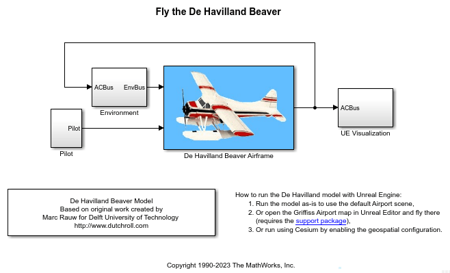
Fly the De Havilland Beaver with Unreal Engine Visualization
This example shows how to model the De Havilland Beaver using Simulink®, Aerospace Blockset™, and Simulink® 3D Animation™ software with Unreal Engine® (UE) visualization. It shows how to use a pilot joystick to fly the De Havilland Beaver in the Airport or Griffiss Airport scenes or the Cesium Ion® environment.
The De Havilland Beaver model includes airframe dynamics and aerodynamics. This also models effects of the atmosphere, such as wind profiles for the landing phase.
The Fly the De Havilland Beaver example interfaces with the FlightGear flight simulator. This example explores the use of UE visualization.
Note: This example is not supported in Simulink Online.
Explore UE Visualization
To begin the conversion, open the De Havilland Beaver Airframe > Aircraft Dynamics subsystem and add the pilot commands to ACBus to include the control surface movements in the visualization.
Replace the three animation and FlightGear blocks on the right side of the model with a single subsystem called "UE Visualization" that takes the ACBus as input.
In the new UE Visualization subsystem, add a Simulation 3D Aircraft block first, and then the Simulation 3D Scene Configuration block. Double-click the aircraft block and clear Enable altitude and WoW sensors in the Altitude Sensor tab, then click OK.
Add a Simulation 3D Sky Hogg Pack block and connect its output ports to Simulation 3D Aircraft. Open the pack block mask and select the Propeller rotation check box in the Propulsion tab. In the Controls tab press the Select all button, then click OK.
Connect the ACBus input to a bus selector and configure it to output Xe (body location), [phi, theta, psi] (body rotation), and Pilot (actuator commands). Send that data to the pack block and a rotation subsystem as shown.
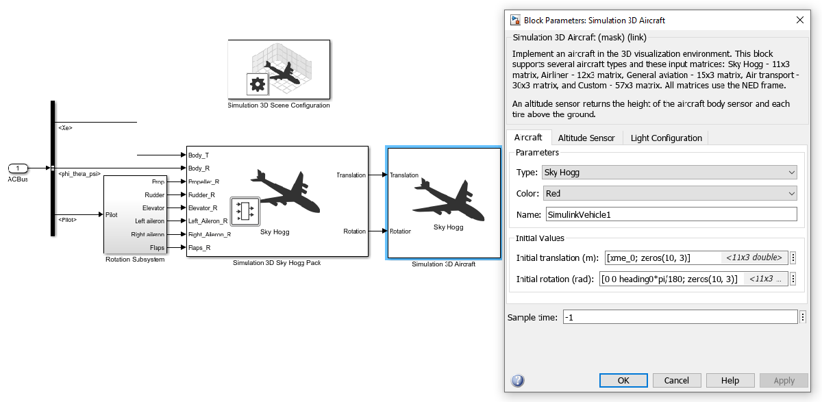
The Sky Hogg aircraft type represents the De Havilland Beaver, although it is a smaller and less massive airframe than the Beaver. To properly visualize the Beaver, create a skeletal mesh for it using the General Aviation skeleton and import that FBX file into Unreal Editor®. For more details, see Prepare Custom Aircraft Mesh for the Unreal Editor and General Aviation.
The Translation and Rotation inputs to the Simulation 3D Aircraft block are sized as [11x3] as required for the Sky Hogg aircraft type. This table shows what part of the aircraft each of these affect. Note that, other than the body, only one rotation of the six degrees of freedom is enabled for each part. 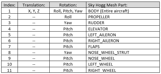
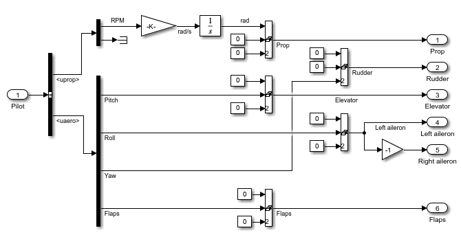
The Rotation Subsystem creates [1x3] row vectors for each of the pilot actuator commands for the propeller RPM, rudder, elevator, left and right ailerons, and flaps. The RPM Gain block multiplies by 2*pi/60 to convert to radians per second.
Open the model.
mdl = "asbdhc2_FlyBeaverUE";
open_system(mdl);
Fly
Before running the model, note that Simulation Pacing has been turned on so that the simulation clock matches the wall clock.
Make sure your joystick is connected.
Click the Run button, then allow a few seconds for the 3D visualization window to initialize.
Use the joystick to fly the aircraft.
Once it is simulating, you can switch between camera views by first left-clicking inside the 3D window, then using the keys
0through9to choose between ten preconfigured camera positions. For flight simulation, views2(behind) and5(cockpit) are the most useful. For more information on camera views, see the Run Simulation section in Customize Scenes Using Simulink and Unreal Editor.
Update to Griffiss Airport Using Custom Scenes and Fly
To fly in the Griffiss Airport (or a custom) scene:
Double-click the Simulation 3D Scene Configuration block to open its mask, and set the Scene source to Unreal Editor.
Enter the Project location, to which you saved the
AutoVrtlEnv.uprojectfile from the support package, then click the Open Unreal Editor button.Click OK to save your changes and close the mask.
Once Unreal Editor opens, change the map to Griffiss Airport by finding the folder MathWorksAerospaceContent Content > Maps and double-clicking
GriffissAirport.
Change the values of the following workspace variables.
xme_0 = [0, 0, -200](place the aircraft 200 meters above the map origin)heading0 = -45(align with runway 33, which is about -45 degrees from true north)
Click the Run button. Once the model has compiled and "Initializing" displays on the bottom bar, click the Play button in Unreal Editor. Allow a few seconds for the connection to be made and simulation to begin.
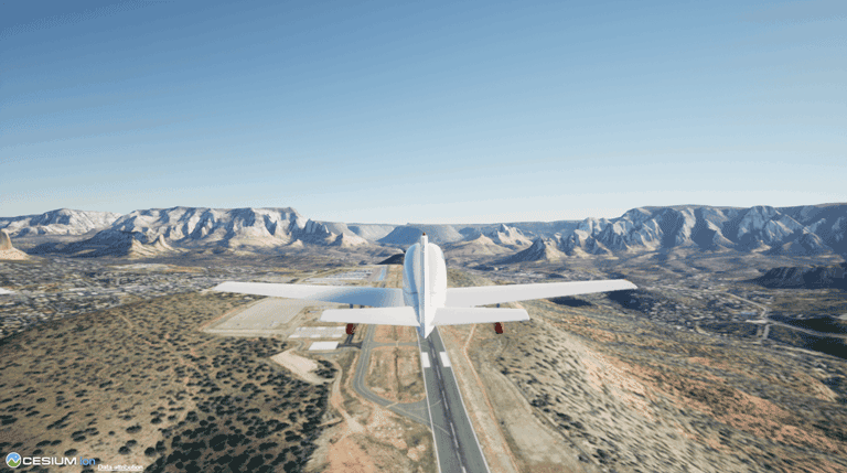
Update to Boston Logan or Sedona Airport using Cesium and Fly
To fly with Cesium, which streams the 3D map and terrain data of a location:
First perform the Visualize with Cesium if you have not already done so. The initial setup includes creating a Cesium Ion account and access token, and creating a new token in the Simulink Authentication Manager to hold your Cesium Ion token.
Open the Simulation 3D Scene Configuration block mask and select Enable geospatial configuration in the Geospatial tab.
Enter your Cesium Ion token name in Access token ID.
Select the Use advanced Sun sky option.
Click Apply to save your changes.
In the Scene tab, for Scene source choose either Default Scenes or Unreal Editor.
If using Unreal Editor for the Scene source, change the map to GeoSpatial by finding the folder MathWorksGeoSpatial Content > Maps and double-clicking
GeoSpatialMap.Click OK to save your changes and close the mask.
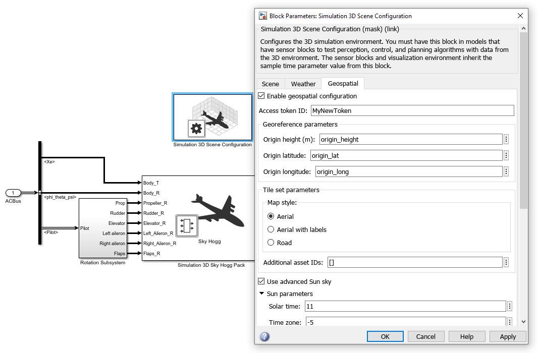
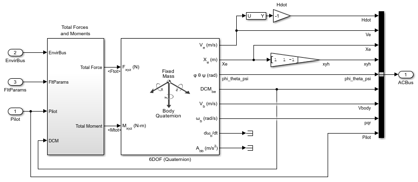
Note the workspace variables for the geospatial origin: origin_height, origin_lat, and origin_long. The initial heading is set by workspace variable heading0 in the 6DOF (Quaternion) block shown in the first figure above. 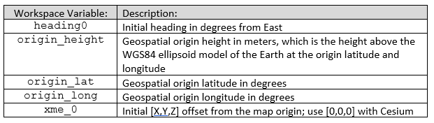
Change the values of the following workspace variables.
xme_0 = [0, 0, 0](no offset used with Cesium Ion)heading0 = -135(to align with Boston Logan airport runway 33, which is about -135 degrees from true east)
Click the Run button, then allow a few seconds for the 3D visualization window to initialize. Cesium Ion takes a few additional seconds for the 3D imagery to load.
The default geospatial origin is runway 33L at Boston Logan airport. To change the initial heading and location, change the values of the heading0 and origin_ variables listed above. For example, for the approach to runway 3 of Sedona Airport, use the following values.
heading0 = -40origin_height = 1500origin_lat = 34.841435origin_long = -111.797380
See Also
Simulation 3D Aircraft | Simulation 3D Scene Configuration