Calculating Compressor Power Required in a Supersonic Wind Tunnel
This example shows how to calculate the required compressor power in a supersonic wind tunnel.
Problem Definition
This section describes the problem to be solved. It also provides necessary equations and known values.
Calculate how much compressor power is required to run a fixed geometry supersonic wind tunnel at steady-state and startup to simulate operating conditions of Mach 2 flow at an altitude of 20 kilometers.
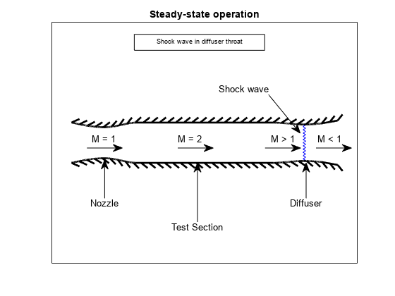
The test section is circular with a diameter of 25 centimeters. After the test section is a fixed-area diffuser. The wind tunnel uses a cooler to reject extra energy that is added to the system by the compressor. Therefore, the compressor inlet and the test section have the same stagnation temperature. Assume the compressor is isentropic and friction effects are negligible.
steadyPicture = plotSupersonicWindTunnel('steady');
The given information in the problem is:
diameter = 25/100;  % Diameter of the cross-section [m]
height   = 20e+03;  % Design altitude [m]
testMach = 2.0;     % Mach number in the test section [dimensionless]
The fluid is assumed to be air and therefore it has the following properties.
k  = 1.4;       % Specific heat ratio [dimensionless]
cp = 1.004;     % Specific heat at constant pressure [kJ / (kg * K)]
The cross-section area of the test section is needed from the diameter.
testSectionArea = pi * (diameter)^2 / 4 ; % [m^2]Because the design altitude is given, solve for the flight conditions at that altitude. The Aerospace Toolbox has several functions to calculate the conditions at various altitudes. One such function, atmosisa, uses the International Standard Atmosphere to calculate the flight conditions on the left hand side given an altitude input:
[testSectionTemp, testSectionSpeedOfSound, testSectionPressure, testSectionDensity] = atmosisa(height);
This function uses the following units:
testSectionTemp = Static temperature in the test section        [K]
testSectionSpeedOfSound = Speed of sound in the test section    [m / s]
testSectionPressure = Static pressure in the test section       [kPa]
testSectionDensity = Density of the fluid in the test section   [kg / m^3]
Calculation of the Stagnation Quantities
You must calculate many of the stagnation (total) quantities in the test section. The ratios of local static conditions to the stagnation conditions can be calculated with flowisentropic.
[~,tempRatioIsen, presRatioIsen, ~, areaRatioIsen] = flowisentropic(k, testMach);
All of the left hand side quantities are dimensionless ratios. Now we can use the ratio of static temperature to stagnation temperature to calculate the stagnation temperature.
testSectionStagTemp = testSectionTemp / tempRatioIsen;
The optimum condition for steady-state operation of a supersonic wind tunnel with a fixed-area diffuser occurs when a normal shock is present at the diffuser throat. For optimum condition, the area of the diffuser throat must be smaller than the area of the nozzle throat. Assuming a perfect gas with constant specific heats, calculate the factor by which the diffuser area must be smaller than the nozzle area. This calculation is from a simplified form of the conservation of mass equation involving total pressures and cross-sectional areas:
where
Rearrange the equation:
This example assumes the nozzle throat area, the test section, and the region of flow at the diffuser throat before the shock to be upstream. Because the shock wave is at the throat of the diffuser, the diffuser throat area can be considered either upstream or downstream of the shock. This example assumes the diffuser throat area to be downstream. Since the upstream flow is isentropic until the shock wave, you can use the test section Mach number as the upstream Mach number. Doing this enables you to calculate the total pressure ratio through the shock and then the area ratio between the nozzle and the diffuser area.
The total pressure ratio is:
Calculate the total pressure ratio using the normal shock function from Aerospace Toolbox:
[~, ~, ~, ~, ~, stagPressRatio] = flownormalshock(k, testMach);
The area ratio at the shock is:
We have the following expression using the conservation of mass as discussed previously.
areaRatioShock = stagPressRatio;
Calculate the area of the diffuser:
diffuserArea = testSectionArea / (areaRatioShock * areaRatioIsen);
Because the diffuser throat area is smaller than the test section area, the Mach number of the flow must converge toward unity. Using flowisentropic with the area ratio as the input, calculate the Mach number just upstream of the shock:
diffuserMachUpstreamOfShock = flowisentropic(k, (1 / areaRatioShock), 'sup');Use flownormalshock to calculate the flow properties through the shock wave. Note, here again, we will only need the total pressure ratio:
[~, ~, ~, ~, ~, P0] = flownormalshock(k, diffuserMachUpstreamOfShock);
Calculation of Work and Power Required for the Steady-State Case
The work done by the compressor per unit mass of fluid equals the enthalpy change through the compressor. From the definition of enthalpy, calculate the specific work done by knowing the temperature change and the specific heat of the fluid at constant pressure:
For an isentropic compressor,
Rearrange the above equation to solve for the temperature difference. Recall that the temperature into the compressor is the same as the test section stagnation temperature.
tempDiff = testSectionStagTemp * ((1 / P0)^((k - 1) / k) - 1); % [K]Now the specific work can be found.
specificWork = cp * tempDiff; % [kJ / kg]The power required equals the specific work times the mass flow rate. During steady-state operation, the mass flow rate through the test section is given by:
where all flow quantities are the values in the test section:
massFlowRate = testSectionDensity * testSectionArea * testMach * testSectionSpeedOfSound; % [kg / s]Finally, calculate the power required by the compressor during steady-state operation.
powerSteadyState = specificWork * massFlowRate; % [kW]Calculating Work and Power Required During Startup
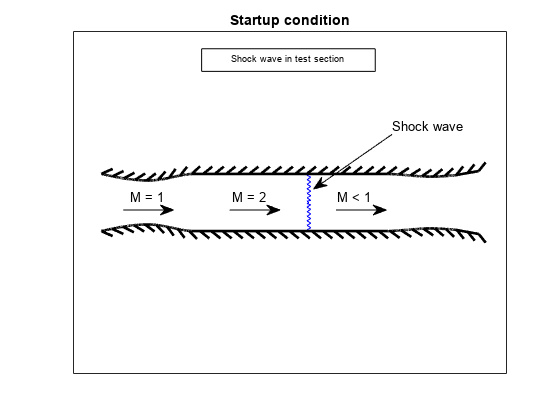
startupPicture = plotSupersonicWindTunnel('startup');
For the startup condition, the shock wave is in the test section. The Mach number immediately before the shock wave is the test section Mach number.
[~, ~, ~, ~, ~, stagPressRatioStartup] = flownormalshock(k, testMach);
Now, calculate the specific work of the isentropic compressor.
specificWorkStartup = cp * testSectionStagTemp * ((1 / stagPressRatioStartup)^((k - 1) / k) - 1); % [kJ / kg]Then, calculate the power required during startup:
powerStartup = specificWorkStartup * massFlowRate; % [kW]The power required during steady-state operation (53.1 kW) is much lower than that required by the compressor during startup (97.9 kW). These power required results represent the optimum and worst-case operation conditions, respectively.
power = [powerSteadyState powerStartup];
barGraph = figure('name','barGraph');
bar(power,0.1);
ylabel('Power required [kilowatts]')
set(gca,'XTickLabel',{'powerSteadyState', 'powerStartup'})
![Figure barGraph contains an axes object. The axes object with ylabel Power required [kilowatts] contains an object of type bar.](../../examples/aero/win64/CalculatingCompressorPowerRequiredInSupersonicWindTunnelExample_03.png)
Reference
[1] James, J. E. A., "Gas Dynamics, Second Edition", Allyn and Bacon, Inc, Boston, 1984.
See Also
atmosisa | flowfanno | flowisentropic | flownormalshock | flowprandtlmeyer