Design Variations of Microstrip Patch Antenna Using PCB Stack
Use the pcbstack to design basic, parasitic, direct-coupled, and CP patch antennas.
Setup parameters.
vp = physconst("lightspeed");
f = 850e6;
lambda = vp./f;
Design Basic Patch Antenna
Set the length and width of the patch and the groundplane.
Lp = lambda(1)/2;
Wp = lambda(1)/2;
Lgp = 0.75.*lambda(1);
Wgp = 0.75.*lambda(1);
h = 2.e-3;
p1 = antenna.Rectangle(Length=Lp, Width=Wp, NumPoints=30);
p2 = antenna.Rectangle(Length=Lgp, Width=Wgp);
d1 = dielectric("Air");
Define the properties of the PCB stack.
basicPatch = pcbStack;
basicPatch.Name = "Basic Patch";
basicPatch.BoardThickness = h;
d1.Thickness = h;
basicPatch.BoardShape = p2;
basicPatch.Layers = {p1,d1,p2};
basicPatch.FeedLocations = [-lambda(1)/8 0 1 3];
figure
show(basicPatch)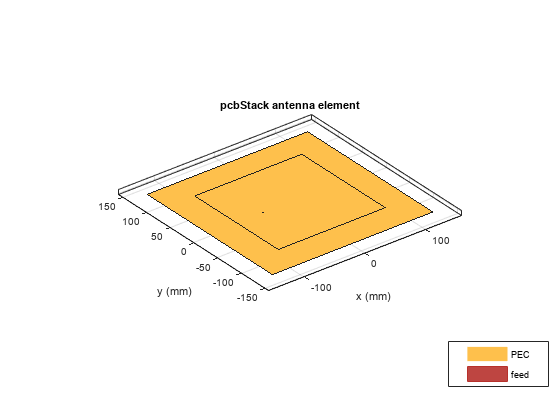
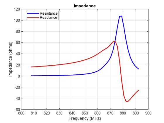
Plot the impedance of the basic patch antenna.
freq1 = linspace(f(1)-0.05*f(1),f(1) + 0.05*f(1),51);
figure
impedance(basicPatch,freq1)
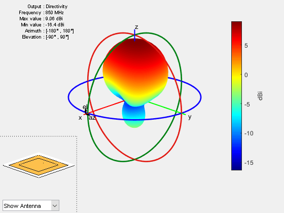
Plot the radiation pattern of the basic patch antenna.
figure
pattern(basicPatch,f(1))
Design Parasitic Patch Antenna
Set the dimensions for the patch.
L = 0.15;
W = 1.5*L;
stripL = L;
gapx = 0.015;
gapy = 0.01;
r1 = antenna.Rectangle(Center=[0 0], Length=L, Width=W);
r2 = antenna.Rectangle(Center=[L/2+stripL/2+gapx 0], Length=stripL,...
    Width=W, NumPoints=[2 20 2 20]);
r3 = antenna.Rectangle(Center=[-L/2-stripL/2-gapx 0], Length=stripL,...
    Width=W, NumPoints=[2 20 2 20]);
r = r1 + r2 + r3;
figure
show(r)

Set the dimensions of the groundplane.
Lgp = 0.55;
Wgp = 0.4;
g1  = antenna.Rectangle(Center=[0 0], Length=Lgp, Width=Wgp);
Define the properties of the PCB stack. Create a pcb stack by driving the center radiator.
parasitic_patch = pcbStack;
parasitic_patch.BoardShape = g1;
parasitic_patch.BoardThickness = 0.007;
parasitic_patch.Layers = {r,g1};
parasitic_patch.FeedLocations = [(L)/4 0 1 2];
figure
show(parasitic_patch)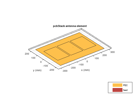
Plot the S-parameters of the parasitic patch antenna.
s = sparameters(parasitic_patch,linspace(0.8e9,1e9,11));
figure
rfplot(s)

Plot the radiation pattern of the parasitic patch antenna.
figure
pattern(parasitic_patch,0.896e9)

Design Direct-coupled Patch Antenna
r2 = copy(r1);
r2.Center = [lambda/1.25 0];
r3 = copy(r1);
r3.Center = [-lambda/1.25 0];
r = r1+ r2 + r3;
figure
show(r)

Strip join the sections.
r4 = antenna.Rectangle(Length=0.65*lambda, Width=0.02*lambda,...
    Center=[lambda/2 0], NumPoints=[20 2 20 2]);
r5 = copy(r4);
r5.Center = [-lambda/2 0];
s = r + r4 + r5;
figure
show(s)
Define the properties of the PCB stack.
g1.Length = 0.8;
series_patch = pcbStack;
series_patch.BoardShape = g1;
series_patch.Layers = {s,g1};
series_patch.FeedLocations = [L/4 0 1 2];
figure
show(series_patch)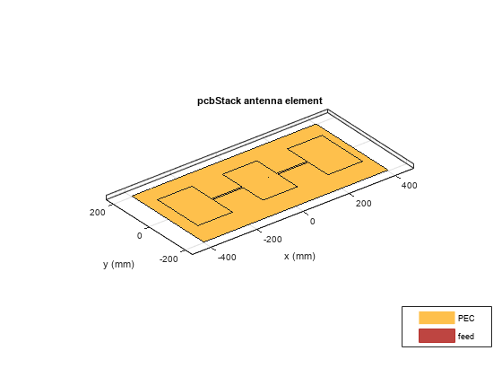
Plot the radiation pattern at 1 GHz for the direct-coupled patch antenna.
figure
pattern(series_patch,1e9)

Mesh the antenna using maximum edge length of 0.03 m.
figure
mesh(series_patch, MaxEdgeLength=0.03)

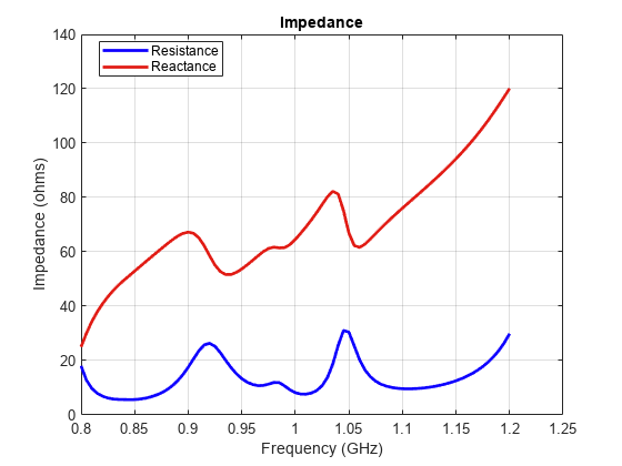
Plot the impedance of the direct-coupled patch antenna for the frequency range, 0.8 GHz to 1.2 GHz.
figure
impedance(series_patch,linspace(0.8e9,1.2e9,81))
Design Circularly Polarized Patch - Truncated Corners
Set the length and width of the patch and the groundplane.
Lp = lambda(1)/2;
Wp = lambda(1)/2;
Lgp = 0.75.*lambda(1);
Wgp = 0.75.*lambda(1);
h = 2.e-3;
Create the base shape for the patch.
p1 = antenna.Rectangle(Length=Lp, Width=Wp, NumPoints=20);
Truncate the corners of the rectangle.
Lcorner = 0.25*Lp;
Wcorner = 0.25*Wp;
cornerCenter1 = [-Lp/2,Wp/2 0];
cornerCenter2 = [Lp/2,-Wp/2 0];
pcorner1 = antenna.Rectangle(Length=Lcorner, Width=Wcorner);
pcorner1 = rotateZ(pcorner1,45);
pcorner1 = translate(pcorner1,cornerCenter1);
pcorner2 = antenna.Rectangle(Length=Lcorner, Width=Wcorner);
pcorner2 = rotateZ(pcorner2,45);
pcorner2 = translate(pcorner2,cornerCenter2);
pradiator = p1 - pcorner1 - pcorner2;
Create the groundplane shape.
p2 = antenna.Rectangle(Length=Lgp, Width=Wgp);
Define the dielectric Layer.
d1 = dielectric("Air");Define the properties of the PCB stack for the circularly polarized patch.
truncatedCornerPatch = pcbStack;
truncatedCornerPatch.Name = "Basic Patch";
truncatedCornerPatch.BoardThickness = h;
d1.Thickness = h;
truncatedCornerPatch.BoardShape = p2;
truncatedCornerPatch.Layers = {pradiator,d1,p2};
truncatedCornerPatch.FeedLocations = [-lambda(1)/8 0 1 3];
figure
show(truncatedCornerPatch)
Plot impedance of the circularly polarized antenna.
figure
impedance(truncatedCornerPatch,freq1)
