Discone Antenna for TV Broadcasting System
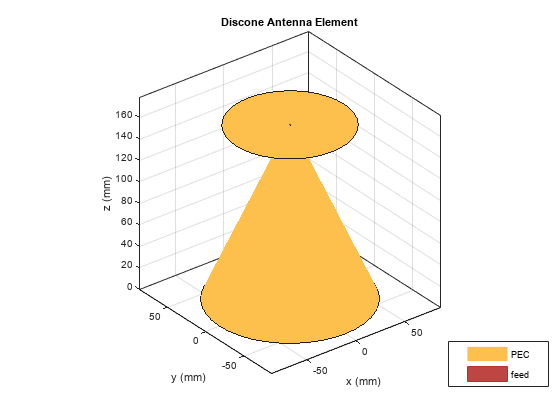
This example shows how to design and implement a discone antenna for indoor use in digital TV receiving and transmitting systems. Discone antennas are wide bandwidth and omnidirectional radiation antennas that are widely used in VHF and UHF broadcasting systems. The antenna consists of a circular disc and a cone whose apex approaches the center of the disc.
Define Parameters
Rd = 55e-3;               % Radius of disc
Rc1 = 72.1e-3;            % Broad Radius of cone
Rc2 = 1.875e-3;           % Narrow Radius of cone
Hc = 160e-3;              % Vertical height of cone
Fw = 1e-3;                % Feed Width
S = 1.75e-3;              % Spacing between cone and disc
The above dimensions provided in [1] helps to design discone antenna to cover frequencies between 470 and 862 MHz, which is the Ultra High Frequency band of TV broadcasting.
Create Discone Antenna
Create a discone antenna using the defined parameters.
ant = discone;
ant.Height = Hc;
ant.ConeRadii = [Rc2 Rc1];
ant.DiscRadius = Rd;
ant.FeedHeight = S;
ant.FeedWidth = Fw;
figure
show(ant)
title("Discone Antenna Element");
S-Parameters
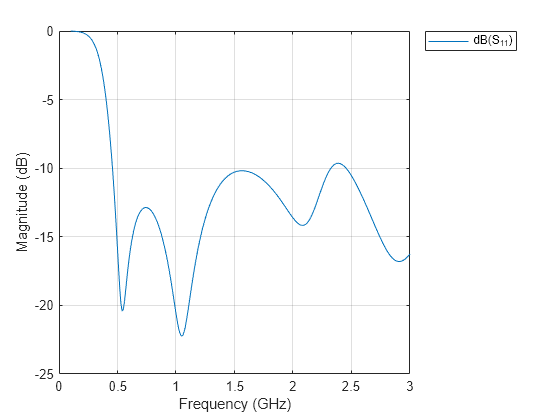
The operational characteristics of the discone antenna are mainly dependent on the broad and narrow radius and the height of the cone. The disc radius and the height of the cone are related to the minimum frequency of operation of the antenna, where the disc should have an overall diameter of 0.7 times a quarter wavelength of the antenna's minimum working frequency. In this example, the minimum operating frequency is 470 MHz. The higher frequency of the discone antenna is mainly determined by the size of the narrow radius of the cone and the gap between the cone and the disc. These dimensions will control the input impedance and is used to guarantee impedance match. Small variations on these dimensions can impose a significant change in the antenna matching.
freq = (0.1:0.01:3)*1e9;
[~] = mesh(ant, MaxEdgeLength=10e-3);
s1 = sparameters(ant,freq);
rfplot(s1);

Antenna is said to be in good performance when the reflection coefficient is below -10 dB. There is a good impedance match from 460 MHz to 2.3 GHz. When you plot the S-parameters over a wide range of frequencies, you can observe wideband characteristics of discone antenna.
Radiation Pattern
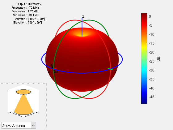
Plot radiation pattern at 470MHz
f = 470e6;
figure
pattern(ant,f);

The pattern is omnidirectional from 470 MHz to 862 MHz, with the gain ranging from 1.75 to 2.3 dBi. Due to omnidirectional characteristics, discone antenna is used in TV broadcasting systems.
Elevation Pattern
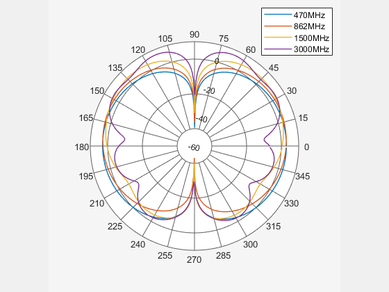
Elevation pattern is the 2D radiation pattern of the antenna.
p1 = patternElevation(ant,470e6);
p2 = patternElevation(ant,862e6);
p3 = patternElevation(ant,1.5e9);
p4 = patternElevation(ant,3e9);
figure
polarpattern(p1);
hold on;
polarpattern(p2);
polarpattern(p3);
polarpattern(p4);
legend ({"470MHz" "862MHz" "1500MHz" "3000MHz"});

The radiation pattern is omnidirectional in azimuth plane and bidirectional in elevation plane.
Conclusion
The antenna provides matched bandwidth, below -10 dB of return loss, between 460 MHz and 2.3 GHz, and provides omnidirectional radiation pattern within the considered TV band, from 470 MHz to 862 MHz. There is good agreement between the simulation results and the results from [1] in terms of directivity of radiation pattern.
References
[1] R.Goncalves, P.Pinho and N.B.Carvalho,"Design and implementation of a 3D printed discone antenna for TV broadcasting system," 2015 IEEE International Symposium on Antennas and Propagation & USNC/URSI National Radio Science Meeting, Vancouver, BC, 2015, pp. 314-315.
[2] Sarita Verma, Abhilasha Mishra, Rukhsana khan, "Analysis of Variation of Various Parameters on Design of Discone Antenna", Advanced Computational Techniques in Electromagnetics, Volume 2012(2012),1-5.
See Also
Design and Analyze VHF/UHF Biconical Antenna for Testing Applications