Plane Wave Excitation - Scattering Solution
This example explains how to excite an antenna using a plane wave. The antenna in this case can be thought of as a receiving antenna. A receiving antenna may be viewed as any metal object that scatters an incident electromagnetic field. As a result of scattering an electric current appears on the antenna's surface. The current in turn creates a corresponding electric field. This produces a voltage difference across the feed. This voltage constitutes the received signal. [1]
Incident Plane Wave on Dipole Antenna
Consider the dipole antenna of length 2 m and width of 50 mm oriented along the z-axis. It is excited by a plane-wave directed along the positive x-axis and having a z-polarization. The inset figure in the top right hand corner shows the direction and polarization of the plane wave with reference to the antenna geometry.
d = dipole(Length=2,Width=50e-3);
p = planeWaveExcitation(Element=d,Direction=[1 0 0],...
    Polarization=[0 0 1]);
show(p)
Visualize Current Distribution
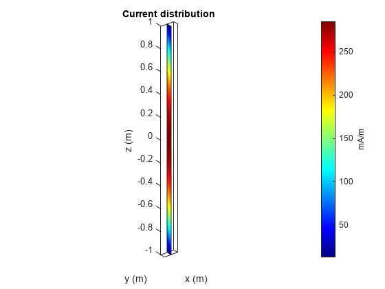
The current function displays the resulting current distribution on the antenna surface. The z-component of the current, along the dipole axis, dominates. The maximum is in the middle of the dipole.
current(p,75e6);

Measure Feed Current
The current at the antenna feed is calculated by determining the current density at the antenna feed and multiplying it with the length of the feed. In this case the current is about 13.9 mA.
I = feedCurrent(p,75e6);
magI = abs(I);
Calculate Voltage at Feed
The feed voltage can be calculated as the product of the feed current and the impedance of the antenna at that frequency. In this case the feed voltage is about 1.45 V. This is the received signal.
Z = impedance(d,75e6);
feedV = abs(Z*I);
Change Polarization of Plane Wave
Change the polarization of the plane wave so that it is y-polarized.
p.Polarization = [0 1 0];
show(p)

In this case feed voltage is about 4.7 mV. The received signal is down by a factor of 300, so the antenna is receiving very little as compared to the previous case.
Icross = feedCurrent(p, 75e6);
feedVcross  = abs(Z*Icross);
This indicates that the dipole antenna is capable of receiving signals whose E-field has a component parallel to the dipole axis. So dipole is a linearly polarized antenna.
Reference
[1] S. N Makarov, Antenna and EM Modeling with MATLAB, chapter 2, Wiley, New York, 2002.