Automated Manual Transmission
Ideal automated manual transmission
Libraries:
Powertrain Blockset /
Transmission /
Transmission Systems
Description
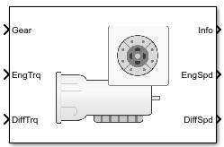
The Automated Manual Transmission block implements an ideal automated transmission (AMT). An AMT is a manual transmission with additional actuators and an electronic control unit (ECU) to regulate clutch and gear selection based on commands from a controller. The number of gears is specified via an integer vector with corresponding gear ratios, inertias, viscous damping, and efficiency factors. The clutch and synchronization engagement rates are linear and adjustable.
Use the block for:
Power and torque capacity sizing
Determining gear ratio impact on fuel economy and performance
To determine the rotational drive shaft speed and reaction torque, the Automated Manual Transmission block calculates:
Clutch lock-up and clutch friction
Locked rotational dynamics
Unlocked rotational dynamics
To specify the block efficiency calculation, for Efficiency factors, select either of these options.
| Setting | Block Implementation |
|---|---|
Gear only | Efficiency determined from a 1D lookup table that is a function of the gear. |
Gear, input torque, input speed, and temperature | Efficiency determined from a 4D lookup table that is a function of:
|
Clutch Control
The AMT delivers drive shaft torque continuously by controlling
the pressure signals from the clutch. If you select Control
type parameter Ideal integrated controller,
the block generates idealized clutch pressure signals. To use your
own clutch control signals, select Control type parameter External
control.
Clutch Lock-Up and Clutch Friction
Based on the clutch lock-up condition, the block implements one of these friction models.
| If | Clutch Condition | Friction Model |
|---|---|---|
| Unlocked | ||
| Locked |
Tf = Ts |
The equations use these variables.
| ωt | Output drive shaft speed |
| ωi | Input drive shaft speed |
| ωd | Drive shaft speed |
Viscous damping | |
| Fc | Applied clutch force |
| N | Engaged gear |
Frictional torque | |
Kinetic frictional torque | |
Static frictional torque | |
Effective clutch radius | |
Annular disk outer radius | |
Annular disk inner radius | |
| μs | Coefficient of static friction |
| μk | Coefficient of kinetic friction |
Locked Rotational Dynamics
To model the rotational dynamics when the clutch is locked, the block implements these equations.
The block determines the input torque, Ti, through differentiation.
The equations use these variables.
| ωi | Input drive shaft speed |
| ωd | Drive shaft speed |
| N | Engaged gear |
| bN | Engaged gear viscous damping |
| JN | Engaged gear inertia |
| ηN | Engaged gear efficiency |
| Td | Drive shaft torque |
| Ti | Applied input torque |
Unlocked Rotational Dynamics
To model the rotational dynamics when the clutch is unlocked, the block implements this equation.
where:
| ωd | Drive shaft speed |
| N | Engaged gear |
| bN | Engaged gear viscous damping |
| JN | Engaged gear inertia |
| Td | Drive shaft torque |
| Ti | Applied input torque |
Power Accounting
For the power accounting, the block implements these equations.
| Bus Signal | Description | Variable | Equations | ||
|---|---|---|---|---|---|
|
|
| Engine power | Peng | |
PwrDiffrntl | Differential power | Pdiff | |||
|
| PwrEffLoss | Mechanical power loss | Peffloss | ||
PwrDampLoss | Mechanical damping loss | Pdamploss | |||
PwrCltchLoss | Clutch power loss | Pmech | When locked: When unlocked: | ||
|
| PwrStoredTrans | Rate change in rotational kinetic energy | Pstr | When locked: When unlocked: | |
The equations use these variables.
| bN | Engaged gear viscous damping |
| JN | Engaged gear rotational inertia |
| Jin | Flywheel rotational inertia |
| ηN | Engaged gear efficiency |
| N | Engaged gear ratio |
| Ti | Applied input torque, typically from the engine crankshaft or dual mass flywheel damper |
| Td | Applied load torque, typically from the differential or drive shaft |
| ωd | Initial input drive shaft rotational velocity |
| ωi, ώi | Applied drive shaft angular speed and acceleration |
Examples
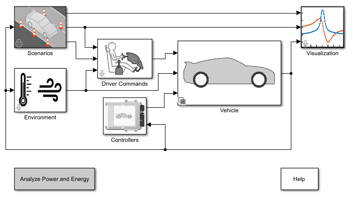
Build Conventional Vehicle Model
Build a vehicle with an internal combustion engine using the conventional vehicle reference application.
Ports
Input
Output
Parameters
Extended Capabilities
Version History
Introduced in R2017a