Main Content

Compressor

Compressor for boosted engines

  • Compressor block

Libraries:
Powertrain Blockset / Propulsion / Combustion Engine Components / Boost

Description

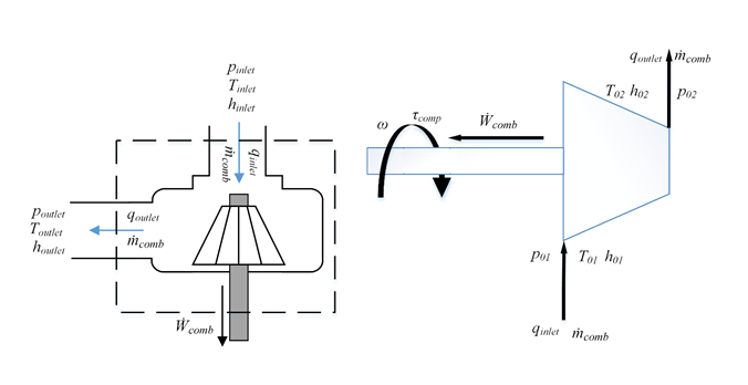
The Compressor block simulates engine boost by using the drive shaft energy to increase the intake manifold pressure. The block is a component of supercharger and turbocharger models. The block uses two-way ports to connect to the inlet and outlet control volumes and the drive shaft. The control volumes provide the pressure, temperature, and specific enthalpy for the compressor to calculate the mass and energy flow rates. To calculate the torque and flow rates, the drive shaft provides the speed to the compressor. Typically, compressor manufacturers provide the mass flow rate and efficiency tables as a function of corrected speed and pressure ratio. You can specify the lookup tables to calculate the mass flow rate and efficiency. The block does not support reverse mass flow.

If you have Model-Based Calibration Toolbox™, click Calibrate Performance Maps to virtually calibrate the mass flow rate and turbine efficiency lookup tables using measured data.

The mass flows from the inlet control volume to the outlet control volume.
Virtual Calibration

If you have Model-Based Calibration Toolbox, click Calibrate Performance Maps to virtually calibrate the mass flow rate and turbine efficiency lookup tables using measured data. The dialog box steps through these tasks.

Task

Description

Import compressor data

Import this compressor data from a file. For more information, see Using Data (Model-Based Calibration Toolbox).

  • Speed, Spd, in rad/s

  • Mass flow rate, MassFlwRate, in kg/s

  • Pressure ratio, PrsRatio, dimensionless

  • Efficiency, Eff, dimensionless

The speed, mass flow rate, pressure ratio, and efficiency are in the 2nd-5th columns of the data file, respectively. The first and second rows of the data file provide the variable names and units. For example, use this format.

Name:SpdMassFlwRatePrsRatioEff
Unit:rad/skg/s  
Data:8373.30.021.210.44
 

...

.........

Model-Based Calibration Toolbox limits the speed and pressure ratio breakpoint values to the maximum values in the file.

To filter or edit the data, select Edit in Application. The Model-Based Calibration Toolbox Data Editor opens.

Generate response models

Model-Based Calibration Toolbox fits the imported data to the response models.

Data

Response Model

Mass flow rate

Extended ellipse response model described in Modeling and Control of Engines and Drivelines2

Efficiency

Polynomial

To assess or adjust the response model fit, select Edit in Application. The Model-Based Calibration Toolbox Model Browser opens. For more information, see Model Assessment (Model-Based Calibration Toolbox).

Generate calibration

Model-Based Calibration Toolbox calibrates the response model and generates calibrated tables.

To assess or adjust the calibration, select Edit in Application. The Model-Based Calibration Toolbox CAGE Browser opens. For more information, see Calibration Lookup Tables (Model-Based Calibration Toolbox).

Update block parameters

Update these mass flow rate and efficiency parameters with the calibration.

  • Corrected mass flow rate table, mdot_corr_tbl

  • Efficiency table, eta_comp_tbl

  • Corrected speed breakpoints, w_corr_bpts1

  • Pressure ratio breakpoints, Pr_bpts2

Thermodynamics

The block uses these equations to model the thermodynamics.

CalculationEquations
Forward mass flow

m˙comp>0

p01=pinlet

p02=poutlet

T01=Tinlet

h01=hinlet

First law of thermodynamics

W˙comp=m˙compcp(T01T02)

Isentropic efficiency

ηcomp=h02sh01h02h01=T02sT01T02T01

Isentropic outlet temperature, assuming ideal gas and constant specific heats

T02s=T01(p02p01)γ1γ

Specific heat ratio

γ=cpcpR

Outlet temperature

T02=T01+T01ηcomb{(p02p01)γ1γ1}

Heat flows

qinlet=m˙comph01

qoutlet=m˙comph02=m˙compcpT02

Corrected mass flow rate

m˙corr=m˙compT01/Trefp01/pref

Corrected speed

ωcorr=ωT01/Tref

Pressure ratio

pr=p01p02

The block uses the internal signal FlwDir to track the direction of the flow.

The equations use these variables.

pinlet, p01

Inlet control volume total pressure

Tinlet, T01

Inlet control volume total temperature

hinlet, h01

Inlet control volume total specific enthalpy

poutlet, p02

Outlet control volume total pressure

Toutlet

Outlet control volume total temperature

houtlet

Outlet control volume total specific enthalpy

W˙comp

Drive shaft power

T02

Outlet total temperature

h02

Outlet total specific enthalpy

m˙comp

Mass flow rate through compressor

qinlet

Inlet heat flow rate

qoutlet

Outlet heat flow rate

ηcomp

Compressor isentropic efficiency

T02s

Isentropic outlet total temperature

h02s

Isentropic outlet total specific enthalpy

R

Ideal gas constant

cp

Specific heat at constant pressure

γ

Specific heat ratio

m˙corr

Corrected mass flow rate

ω

Drive shaft speed

ωcorr

Corrected drive shaft speed

Tref

Lookup table reference temperature

Pref

Lookup table reference pressure

τcomp

Compressor drive shaft torque

pr

Pressure ratio

ηcomb,tbl

Compressor efficiency 3-D lookup table

m˙corr,tbl

Corrected mass flow rate 3-D lookup table

ωcorr,bpts1

Corrected speed breakpoints

pr,bpts2

Pressure ratio breakpoints

Power Accounting

For the power accounting, the block implements these equations.

Bus Signal DescriptionEquations

PwrInfo

PwrTrnsfrd — Power transferred between blocks

  • Positive signals indicate flow into block

  • Negative signals indicate flow out of block

PwrDriveshft

Power transmitted from the shaft

W˙turb

PwrHeatFlwIn

Heat flow rate at port A

qoutlet

PwrHeatFlwOut

Heat flow rate at port B

qoutlet

PwrNotTrnsfrd — Power crossing the block boundary, but not transferred

  • Positive signals indicate an input

  • Negative signals indicate a loss

PwrLoss

Power loss

qinletqoutlet+W˙turb

PwrStored — Stored energy rate of change

  • Positive signals indicate an increase

  • Negative signals indicate a decrease

Not used

The equations use these variables.

W˙turb

Drive shaft power

qoutlet

Total outlet heat flow rate

qinlet

Total inlet heat flow rate

Examples

Ports

Input

expand all

ShftSpd — Signal containing the drive shaft angular speed, ω, in rad/s.

Bus containing the inlet control volume:

  • InPrs — Pressure, pinlet, in Pa

  • InTemp — Temperature, Tinlet, in K

  • InEnth — Specific enthalpy, hinlet, in J/kg

Bus containing the outlet control volume:

  • OutPrs — Pressure, poutlet, in Pa

  • OutTemp — Temperature, Toutlet, in K

  • OutEnth — Specific enthalpy, houtlet, in J/kg

Output

expand all

Bus signal containing these block calculations.

SignalDescriptionUnits

CmprsOutletTemp

Temperature exiting the compressor

K

DriveshftPwr

Drive shaft power

W

DriveshftTrq

Drive shaft torque

N·m

CmprsMassFlw

Mass flow rate through compressor

kg/s

PrsRatio

Pressure ratio

N/A

DriveshftCorrSpd

Corrected drive shaft speed

rad/s

CmprsEff

Compressor isentropic efficiency

N/A

CorrMassFlw

Corrected mass flow rate

kg/s

PwrInfo

PwrTrnsfrdPwrDriveshft

Power transmitted from the shaft

W

PwrHeatFlwIn

Heat flow rate at port A

W
PwrHeatFlwOut

Heat flow rate at port B

W
PwrNotTrnsfrdPwrLoss

Power loss

W
PwrStored

Not used

W

Trq — Signal containing the drive shaft torque, τcomp, in N·m.

Bus containing:

  • MassFlwRate — Mass flow rate through inlet,m˙comp, in kg/s

  • HeatFlwRate — Inlet heat flow rate, qinlet, in J/s

  • Temp — Inlet temperature, in K

  • MassFrac — Inlet mass fractions, dimensionless.

    Specifically, a bus with these mass fractions:

    • O2MassFrac — Oxygen

    • N2MassFrac — Nitrogen

    • UnbrndFuelMassFrac — Unburned fuel

    • CO2MassFrac — Carbon dioxide

    • H2OMassFrac — Water

    • COMassFrac — Carbon monoxide

    • NOMassFrac — Nitric oxide

    • NO2MassFrac — Nitrogen dioxide

    • NOxMassFrac — Nitric oxide and nitrogen dioxide

    • PmMassFrac — Particulate matter

    • AirMassFrac — Air

    • BrndGasMassFrac — Burned gas

Bus containing:

  • MassFlwRate — Outlet mass flow rate, m˙comp, in kg/s

  • HeatFlwRate — Outlet heat flow rate, qoutlet, in J/s

  • Temp — Outlet temperature, in K

  • MassFrac — Outlet mass fractions, dimensionless.

    Specifically, a bus with these mass fractions:

    • O2MassFrac — Oxygen

    • N2MassFrac — Nitrogen

    • UnbrndFuelMassFrac — Unburned fuel

    • CO2MassFrac — Carbon dioxide

    • H2OMassFrac — Water

    • COMassFrac — Carbon monoxide

    • NOMassFrac — Nitric oxide

    • NO2MassFrac — Nitrogen dioxide

    • NOxMassFrac — Nitric oxide and nitrogen dioxide

    • PmMassFrac — Particulate matter

    • AirMassFrac — Air

    • BrndGasMassFrac — Burned gas

Parameters

expand all

Performance Tables

If you have Model-Based Calibration Toolbox, click Calibrate Performance Maps to virtually calibrate the mass flow rate and turbine efficiency lookup tables using measured data. The dialog box steps through these tasks.

Task

Description

Import compressor data

Import this compressor data from a file. For more information, see Using Data (Model-Based Calibration Toolbox).

  • Speed, Spd, in rad/s

  • Mass flow rate, MassFlwRate, in kg/s

  • Pressure ratio, PrsRatio, dimensionless

  • Efficiency, Eff, dimensionless

The speed, mass flow rate, pressure ratio, and efficiency are in the 2nd-5th columns of the data file, respectively. The first and second rows of the data file provide the variable names and units. For example, use this format.

Name:SpdMassFlwRatePrsRatioEff
Unit:rad/skg/s  
Data:8373.30.021.210.44
 

...

.........

Model-Based Calibration Toolbox limits the speed and pressure ratio breakpoint values to the maximum values in the file.

To filter or edit the data, select Edit in Application. The Model-Based Calibration Toolbox Data Editor opens.

Generate response models

Model-Based Calibration Toolbox fits the imported data to the response models.

Data

Response Model

Mass flow rate

Extended ellipse response model described in Modeling and Control of Engines and Drivelines2

Efficiency

Polynomial

To assess or adjust the response model fit, select Edit in Application. The Model-Based Calibration Toolbox Model Browser opens. For more information, see Model Assessment (Model-Based Calibration Toolbox).

Generate calibration

Model-Based Calibration Toolbox calibrates the response model and generates calibrated tables.

To assess or adjust the calibration, select Edit in Application. The Model-Based Calibration Toolbox CAGE Browser opens. For more information, see Calibration Lookup Tables (Model-Based Calibration Toolbox).

Update block parameters

Update these mass flow rate and efficiency parameters with the calibration.

  • Corrected mass flow rate table, mdot_corr_tbl

  • Efficiency table, eta_comp_tbl

  • Corrected speed breakpoints, w_corr_bpts1

  • Pressure ratio breakpoints, Pr_bpts2

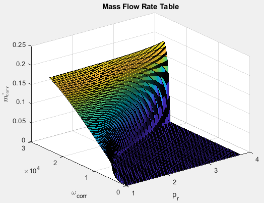
Corrected mass flow rate lookup table, m˙corr,tbl, as a function of corrected driveshaft speed, ωcorr, and pressure ratio, pr, in kg/s.

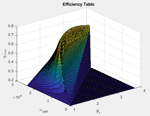
Efficiency lookup table, ηcomb,tbl, as a function of corrected driveshaft speed, ωcorr, and pressure ratio, pr, dimensionless.

Corrected drive shaft speed breakpoints, ωcorr,bpts1, in rad/s.

Pressure ratio breakpoints, pr,bpts2.

Lookup table reference temperature, Tref, in K.

Lookup table reference pressure, Pref, in Pa.

Gas Properties

Ideal gas constant, R, in J/(kg*K).

Specific heat at constant pressure, cp, in J/(kg*K).

References

[1] Heywood, John B. Internal Combustion Engine Fundamentals. New York: McGraw-Hill, 1988.

[2] Eriksson, Lars and Lars Nielsen. Modeling and Control of Engines and Drivelines. Chichester, West Sussex, United Kingdom: John Wiley & Sons Ltd, 2014.

Extended Capabilities

C/C++ Code Generation
Generate C and C++ code using Simulink® Coder™.

Version History

Introduced in R2017a