Heat Exchanger
Intercooler or exhaust gas recirculation (EGR) cooler
Libraries:
Powertrain Blockset /
Propulsion /
Combustion Engine Components /
Fundamental Flow
Description
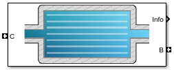
The Heat Exchanger block models a heat exchanger, for example, an intercooler or exhaust gas recirculation (EGR) cooler. The inlet (port C) connects to an engine flow component (flow restriction, compressor, turbine, or engine block). The outlet (port B) connects to a volume (control volume or environment). Based on the upstream temperature, heat exchanger effectiveness, and cooling medium temperature, the block determines the heat transfer rate and downstream temperature.
For the heat exchanger effectiveness and cooling medium temperature, you can specify either a constant value or an external input. For example, if you specify a heat exchanger effectiveness that is:
Equal to 1, the downstream temperature is equal to the cooling medium temperature.
Equal to 0, there is no heat transfer to the cooling medium. The downstream temperature is equal to the upstream temperature.
The block assumes no pressure drop. To model pressure losses, use a Flow Restriction block.
Equations
The Heat Exchanger block implements equations that use these variables.
Upstream temperature | |
Downstream temperature | |
Cooling medium temperature | |
Constant cooling medium temperature | |
External input cooling medium temperature | |
Heat exchanger effectiveness | |
Constant heat exchanger effectiveness | |
Input heat exchanger effectiveness | |
Specific heat at constant pressure | |
Heat exchanger heat transfer rate | |
Pressure at inlet | |
Pressure at outlet | |
Temperature at outlet | |
Specific enthalpy at outlet | |
Heat flow rate at inlet | |
Heat flow rate at outlet | |
Heat exchanger mass flow rate | |
Temperature at inlet | |
Heat exchanger inlet temperature | |
Heat exchanger outlet temperature | |
Inlet specific enthalpy |
Heat exchanger effectiveness measures the effectiveness of heat transfer from the incoming hot fluid to the cooling medium:
In an ideal heat exchanger, the downstream temperature equals the cooling temperature. The effectiveness is equal to 1.
The Heat Exchanger block uses the effectiveness to determine the downstream temperature and heat transfer rate.
Since the block assumes no pressure drop, .
The flow component connection to the heat exchanger inlet determines the direction of the mass flow. Based on the mass flow rate direction, these temperature and heat flow equations apply.
| Fluid Flow | Mass Flow Rate | Temperatures and Heat Flow |
|---|---|---|
Forward — From engine flow component to outlet volume |
|
|
Reverse — From outlet volume to engine flow component |
|
|
The block uses the internal signal FlwDir to track the direction of the flow.
Power Accounting
For the power accounting, the block implements these equations.
| Bus Signal | Description | Equations | ||
|---|---|---|---|---|
|
|
| Heat flow rate at port C | qin |
| Heat flow rate at port B | -qout | ||
|
|
| Heat transfer rate to cooling medium | -qht | |
|
| Not used | |||
Examples
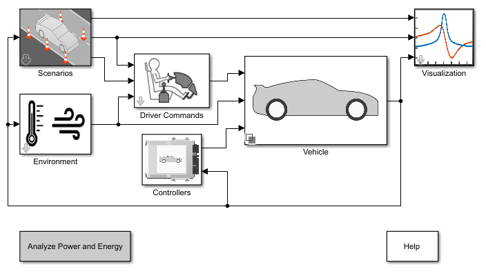
Build Conventional Vehicle Model
Build a vehicle with an internal combustion engine using the conventional vehicle reference application.
Ports
Input
Output
Parameters
References
[1] Eriksson, Lars and Nielsen, Lars. Modeling and Control of Engines and Drivelines. Chichester, West Sussex, United Kingdom: John Wiley & Sons Ltd, 2014.
Extended Capabilities
Version History
Introduced in R2017a