Main Content

Open Differential

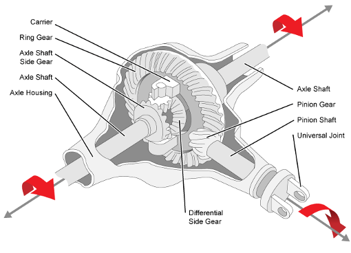
Differential as a planetary bevel gear

  • Open Differential block

Libraries:
Powertrain Blockset / Drivetrain / Final Drive Unit
Vehicle Dynamics Blockset / Powertrain / Drivetrain / Final Drive Unit

Description

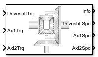
The Open Differential block implements a differential as a planetary bevel gear train. The block matches the driveshaft bevel gear to the crown (ring) bevel gear. You can specify:

  • Carrier-to-driveshaft ratio

  • Crown wheel location

  • Viscous and damping coefficients for the axles and carrier

Use the Open Differential block to:

  • Dynamically couple the post-transmission driveshaft to the wheel axles or universal joints

  • Model simplified or older drivetrains when optimal traction control does not require passive or active torque vectoring

  • Model mechanical power splitting in generic gearbox and drive line scenarios

The block is suitable for use in hardware-in-the-loop (HIL) and optimization workflows. All the parameters are tunable.

The block uses a coordinate system that produces positive tire and vehicle motion for standard engine, transmission, and differential configurations. The arrows indicate positive motion.
Transmission diagram

Efficiency

To account for the block efficiency, use the Efficiency factors parameter. This table summarizes the block implementation for each setting.

SettingImplementation

Constant

Constant efficiency that you can set with the Constant efficiency factor, eta parameter.

Driveshaft torque, temperature and speed

Efficiency as a function of base gear input torque, air temperature, and driveshaft speed. Use these parameters to specify the lookup table and breakpoints:

  • Efficiency lookup table, eta_tbl

  • Efficiency torque breakpoints, Trq_bpts

  • Efficiency speed breakpoints, omega_bpts

  • Efficiency temperature breakpoints, Temp_bpts

For the air temperature, you can either:

  • Select Input ambient temperature to create an input port.

  • Set a Ambient temperature, Tamb parameter value.

To select the interpolation method, use the Interpolation method parameter. For more information, see Interpolation Methods.

Power Accounting

For the power accounting, the block implements these equations.

Bus Signal DescriptionEquations

PwrInfo

PwrTrnsfrd — Power transferred between blocks

  • Positive signals indicate flow into block

  • Negative signals indicate flow out of block

PwrDriveshft

Mechanical power from driveshaft

ηTdωd

PwrAxl1

Mechanical power from axle 1

ηT1ω1

PwrAxl2

Mechanical power from axle 2

ηT2ω2

PwrNotTrnsfrd — Power crossing the block boundary, but not transferred

  • Positive signals indicate an input

  • Negative signals indicate a loss

PwrMechLoss

Total power loss

W˙loss= (Pt+Pd)+PsPt=ηTdωd+ηT1ω1+ηT2ω2

PwrDampLoss

Power loss due to damping

Pd=(b1|ω1|+b2|ω2|+bd|ωd|)

PwrStored — Stored energy rate of change

  • Positive signals indicate an increase

  • Negative signals indicate a decrease

PwrStoredShft

Rate change of stored internal energy

Ps=(ω1ω˙1J1+ω2ω˙2J2+ωdω˙dJd)

Dynamics

The Open Differential block implements these differential equations to represent the mechanical dynamic response for the crown gear, left axle, and right axle.

Mechanical Dynamic ResponseDifferential Equation
Crown Gear

ω˙dJd=ηTd-ωdbd-Ti

Left Axle

ω˙1J1=ηT1-ω1b1-Ti1

Right Axle

ω˙2J2=ηT2-ω2b2-Ti2

The Open Differential block assumes rigid coupling between the crown gear and axles. These constraint equations apply.

ηTi1= ηTi2=N2Ti

ωd=N2(ω1+ω2)

The equations use these variables.

N

Carrier-to-driveshaft gear ratio

Jd

Rotational inertia of the crown gear assembly

bd

Crown gear linear viscous damping

ωd

Driveshaft angular speed

η

Differential efficiency

J1

Axle 1 rotational inertia

b1

Axle 1 linear viscous damping

ω1

Axle 1 speed

J2

Axle 2 rotational inertia

b2

Axle 2 linear viscous damping

ω2

Axle 2 angular speed

Td

Driveshaft torque

T1

Axle 1 torque

T2

Axle 2 torque

Ti

Driveshaft internal resistance torque

Ti1

Axle 1 internal resistance torque

Ti2

Axle 2 internal resistance torque

Ports

Inputs

expand all

Applied input torque, typically from the engine crankshaft, in N·m.

Axle 1 torque, T1, in N·m.

Axle 2 torque, T2, in N·m.

Temperature, in K.

Dependencies

To enable this port:

  • Set Efficiency factors to Driveshaft torque, speed and temperature.

  • Select Input temperature.

Output

expand all

Bus signal containing these block calculations.

SignalDescriptionUnits

Driveshft

DriveshftTrq

Driveshaft torque

N·m

DriveshftSpd

Driveshaft speed

rad/s

Axl1

Axl1Trq

Axle 1 torque

N·m

Axl1Spd

Axle 1 speed

rad/s

Axl2

Axl2Trq

Axle 2 torque

N·m

Axl2Spd

Axle 2 speed

rad/s

PwrInfo

PwrTrnsfrd

PwrDriveshft

Mechanical power from driveshaft

W

PwrAxl1

Mechanical power from axle 1

W

PwrAxl2

Mechanical power from axle 2

W

PwrTrnsfrd

PwrMechLoss

Total power loss

W

PwrDampLoss

Power loss due to damping

W

PwrStored

PwrStoredShft

Rate change of stored internal energy

W

Driveshaft angular speed, ωd, in rad/s.

Axle 1 angular speed, ω1, in rad/s.

Axle 2 angular speed, ω2, in rad/s.

Parameters

expand all

Block Options

To account for the block efficiency, use the Efficiency factors parameter. This table summarizes the block implementation for each setting.

SettingImplementation

Constant

Constant efficiency that you can set with the Constant efficiency factor, eta parameter.

Driveshaft torque, temperature and speed

Efficiency as a function of base gear input torque, air temperature, and driveshaft speed. Use these parameters to specify the lookup table and breakpoints:

  • Efficiency lookup table, eta_tbl

  • Efficiency torque breakpoints, Trq_bpts

  • Efficiency speed breakpoints, omega_bpts

  • Efficiency temperature breakpoints, Temp_bpts

For the air temperature, you can either:

  • Select Input ambient temperature to create an input port.

  • Set a Ambient temperature, Tamb parameter value.

To select the interpolation method, use the Interpolation method parameter. For more information, see Interpolation Methods.

For more information, see Interpolation Methods.

Dependencies

To enable this parameter, set Efficiency factors to Driveshaft torque, speed and temperature.

Select to create input port Temp for the temperature.

Dependencies

To enable this parameter, set Efficiency factors to Driveshaft torque, speed and temperature.

Specify the crown wheel connection to the driveshaft.

Carrier-to-driveshaft gear ratio, N, dimensionless.

Rotational inertia of the crown gear assembly, Jd, in kg·m^2. You can include the driveshaft inertia.

Crown gear linear viscous damping, bd, in N·m·s/rad.

Axle 1 rotational inertia, J1, in kg·m^2.

Axle 1 linear viscous damping, b1, in N·m·s/rad.

Axle 2 rotational inertia, J2, in kg·m^2.

Axle 2 linear viscous damping, b2, in N·m·s/rad.

Axle 1 initial velocity, ωo1, in rad/s.

Axle 2 initial velocity, ωo2, in rad/s.

Efficiency

Constant efficiency, η.

Dependencies

To enable this parameter, set Efficiency factors to Constant.

Dimensionless array of values for efficiency as a function of:

  • M input torques

  • N input speed

  • L air temperatures

Each value specifies the efficiency for a specific combination of torque, speed, and temperature. The array size must match the dimensions defined by the torque, speed, and temperature breakpoint vectors.

Dependencies

To enable this parameter, set Efficiency factors to Driveshaft torque, speed and temperature.

Vector of input torque, breakpoints for efficiency, in N·m.

Dependencies

To enable this parameter, set Efficiency factors to Driveshaft torque, speed and temperature.

Vector of speed, breakpoints for efficiency, in rad/s.

Dependencies

To enable this parameter, set Efficiency factors to Driveshaft torque, speed and temperature.

Vector of ambient temperature breakpoints for efficiency, in K.

Dependencies

To enable this parameter, set Efficiency factors to Driveshaft torque, speed and temperature.

Ambient air temperature, Tair, in K.

Dependencies

To enable this parameter:

  • Set Efficiency factors to Driveshaft torque, speed and temperature.

  • Clear Input ambient temperature.

Extended Capabilities

C/C++ Code Generation
Generate C and C++ code using Simulink® Coder™.

Version History

Introduced in R2017a