Main Content

Torque Converter

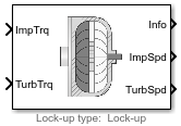
Three-part torque converter consisting of an impeller, turbine, and stator

  • Torque Converter block

Libraries:
Powertrain Blockset / Transmission / Torque Converters

Description

The Torque Converter block implements a three-part torque converter consisting of an impeller, turbine, and stator with an optional clutch lock-up capability. The block can simulate driving (power flowing from impeller to turbine) and coasting (power from turbine dissipated in torque converter hydraulic fluid).

You can specify torque converter characteristics:

  • Speed ratio — Ratio of turbine angular speed to impeller angular speed

  • Torque ratio — Ratio of turbine torque to impeller torque

  • Capacity factor parameterization — Function of input speed or input torque

Optional clutch lock-up configurations include:

  • No lock-up — Model fluid-coupling only

  • Lock-up — Model automatic clutch engagement

  • External lock-up — Model clutch pressure as input from an external signal

Dynamics

Clutch Lock-Up Condition and Clutch Friction

Based on the clutch lock-up condition, the block implements these friction models.

IfClutch ConditionFriction Model
ωiωtorTS<|Jt(Ji+Jt)[Ti+Tfωi(bt+bi)]|UnlockedTf=Tkwhere:Tk=FcReffmktanh[4(ωiωt)]Ts=FcReffmsReff=2(Ro3-Ri3)3(Ro2-Ri2)
ωi=ωtandTS|Jt(Ji+Jt)[Ti+Tf-wt(bt+bi)+wtbt]|Locked

Tf = Ts

Locked Rotational Dynamics

To model the rotational dynamics if the clutch is locked, the block implements equations.

ω˙(Ji+Jt)=Tiω(bi+bt)+Textω=ωi=ωt

The rotational velocity represents both the impeller and turbine rotational velocities.

Unlocked Rotational Dynamics

To model the rotational dynamics if the clutch is unlocked, the block implements equations.

ω˙iJi=TiωibiTfTpω˙tJt=Textωtbt+Tf+TtTp= ωi2ψ(ϕ)Tt= Tpζ(ϕ)

To approximate the torque multiplication lag between the impeller and turbine, you can specify the parameter Fluid torque response time constant (set to 0 to disable), tauc [s].

Power Accounting

For the power accounting, the block implements these equations.

Bus Signal DescriptionVariableEquations

PwrInfo

PwrTrnsfrd — Power transferred between blocks

  • Positive signals indicate flow into block

  • Negative signals indicate flow out of block

PwrImp

Applied impeller power

Pimp

ωiTi
PwrTurb

Applied turbine output power

Pturb

ωtTt

PwrNotTrnsfrd — Power crossing the block boundary, but not transferred

  • Positive signals indicate an input

  • Negative signals indicate a loss

PwrDampLoss

Mechanical damping loss

Pdamploss

btωt2biωi2

PwrFluidCplingLoss

Heat loss to transmission fluid

Pflloss

(TpωiThydωt)

PwrCltchLoss

Clutch slip power loss

Pcltloss

Tk(ωiωt)

PwrStored — Stored energy rate of change

  • Positive signals indicate an increase

  • Negative signals indicate a decrease

PwrStoredImp

Rate change in impeller rotational kinetic energy

Pstrimp

ω˙iωiJi

PwrStoredTurb

Rate change in turbine rotational kinetic energy

Pstrturb

ω˙tωtJt

The block implements equations that use these variables.

Tf

Frictional torque

Tk

Kinetic frictional torque

Ts

Static frictional torque

Ti

Applied input torque

Tp

Impeller reaction torque

Text

Externally applied turbine torque

ψ(ϕ)

Torque conversion capacity factor

ζ(ϕ)

Torque ratio

ωi

Impeller rotational shaft speed

ωt

Turbine rotational shaft speed

Ji

Impeller rotational inertia

Jt

Turbine rotational inertia

bi

Impeller rotational viscous damping

bt

Turbine rotational viscous damping

Reff

Effective clutch radius

Ro

Annular disk outer radius

Ri

Annular disk inner radius

Examples

Ports

Inputs

expand all

Applied input torque, typically from the engine crankshaft or dual mass flywheel, in N·m.

Applied turbine torque, typically from the transmission, in N·m.

Applied clutch force, typically from a hydraulic actuator, in N.

Dependencies

To create this port, select External lock-up input for the Lock-up clutch configuration parameter.

Output

expand all

Bus signal containing these block calculations.

SignalDescriptionUnits

Imp

ImpTrq

Applied input torque

N·m

ImpSpd

Impeller rotational shaft speed

rad/s

Turb

TurbTrq

Applied turbine torque

N·m

TurbSpd

Turbine rotational shaft speed

rad/s

Cltch

CltchForce

Applied clutch force

N

CltchLocked

Clutch locked or unlocked state

N/A

TrqConv

TrqConvSpdRatio

Turbine to impeller speed ratio

N/A

TrqConvEta

Torque conversion efficiency

N/A

PwrInfo

PwrTrnsfrd

PwrImp

Applied impeller power

W

PwrTurb

Applied turbine output power

W

PwrNotTrnsfrd

PwrDampLoss

Mechanical damping loss

W

PwrFluidCplingLoss

Heat loss to transmission fluid

W

PwrCltchLoss

Clutch slip power loss

W

PwrStored

PwrStoredImp

Rate change in impeller rotational kinetic energy

W

PwrStoredTurb

Rate change in turbine rotational kinetic energy

W

Impeller rotational shaft speed, ωi, in rad/s.

Turbine rotational shaft speed, ωt, in rad/s.

Parameters

expand all

Configuration

To ModelSelect
Fluid-coupling onlyNo lock-up
Automatic clutch engagementLock-up
Clutch pressure as input from an external signalExternal lock-up input

Dependencies

To enable the Clutch parameters, select Lock-up or External lock-up input for the Lock-up clutch configuration parameter.

Torque Converter

Impeller shaft inertia, in kg·m^2.

Impeller shaft viscous damping, in N·m·s/rad.

Turbine shaft inertia, in kg·m^2.

Turbine shaft viscous damping, in N·m·s/rad.

Initial impeller shaft velocity, in rad/s.

Initial turbine shaft velocity, in rad/s.

Vector of turbine speed to impeller speed ratios. Breakpoints for the capacity and torque multiplication vectors.

To Set Factor Ratio toSelect
Impeller angular velocity to square root impeller torqueInput speed / sqrt(input torque)
Impeller absorbed torque to square of impeller angular velocityAbsorbed torque / input speed^2

Capacity factor parameterization SettingCapacity Vector Units
Input speed / sqrt(input torque)(rad/s)/(N·m)^0.5
Absorbed torque / input speed^2N·m/(rad/s)^2

Vector of turbine torque to impeller speed ratios.

To account for the delay in torque calculations due to changing input torque, specify the fluid torque transfer time constant, in s.

Interpolates the torque ratio and capacity factor functions between the discrete relative velocity values.

Clutch

The effective radius, Reff, used with the applied clutch friction force to determine the friction force, in m. The effective radius is defined as:

Reff=2(Ro3-Ri3)3(Ro2-Ri2)

The equation uses these variables.

Ro

Annular disk outer radius

Ri

Annular disk inner radius

Dependencies

To enable the Clutch parameters, select Lock-up or External lock-up input for the Lock-up clutch configuration parameter.

Dimensionless clutch disc coefficient of static friction.

Dependencies

To enable the Clutch parameters, select Lock-up or External lock-up input for the Lock-up clutch configuration parameter.

Dimensionless clutch disc coefficient of kinetic friction.

To enable the Clutch parameters, select Lock-up or External lock-up input for the Lock-up clutch configuration parameter.

Dependencies

To enable this parameter, select Lock-up or External lock-up input for the Lock-up clutch configuration parameter.

Set speed ratio threshold that engages clutch lock-up.

Dependencies

To enable this parameter, select Lock-up for the Lock-up clutch configuration parameter.

Set the minimum impeller speed that engages clutch lock-up, in rad/s.

Dependencies

To enable this parameter, select Lock-up for the Lock-up clutch configuration parameter.

Set the minimum impeller speed that disengages clutch lock-up, in rad/s.

Dependencies

To enable this parameter, select Lock-up for the Lock-up clutch configuration parameter.

Open loop clutch lock-up force gain, in N.

Dependencies

To enable this parameter, select Lock-up for the Lock-up clutch configuration parameter.

Open loop clutch lock-up time constant, in s.

Dependencies

To enable this parameter, select Lock-up for the Lock-up clutch configuration parameter.

Extended Capabilities

C/C++ Code Generation
Generate C and C++ code using Simulink® Coder™.

Version History

Introduced in R2017a