Build Hybrid Electric Vehicle P1 Model
The hybrid electric vehicle (HEV) P1 reference application represents a full HEV model with an internal combustion engine, transmission, battery, motor, and associated powertrain control algorithms. Use the reference application for hardware-in-the-loop (HIL) testing, tradeoff analysis, and control parameter optimization of a HEV P1 hybrid. To create and open a working copy of the reference application project, enter
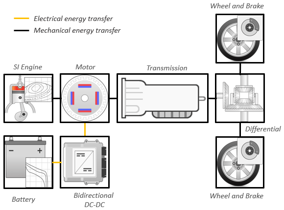
By default, the HEV P1 reference application is configured with:Lithium-ion battery pack
Mapped electric motor
Mapped spark-ignition (SI) engine
This diagram shows the powertrain configuration.
Note
The Virtual Vehicle Composer configures the reference application. If you want to the change the configuration, use the Virtual Vehicle Composer to specify a different powertrain and vehicle.
This table describes the blocks and subsystems in the reference application.
| Reference Application Element | Description |
|---|---|
Analyze Power and Energy | Double-click Analyze Power and Energy to open a live script. Run the script to evaluate and report power and energy consumption at the component- and system-level. For more information about the live script, see Analyze Power and Energy. |
Implements the driver scenario. The subsystem contains variants that generate maneuver-specific driver reference velocity, path, and action signals. | |
Implements the environment model, including road grade, wind velocity, and ambient temperature and pressure. The subsystem contains variants that generate environment- and terrain-specific signals. | |
Implements the driver model that generates acceleration, braking, gear, and steering commands. The subsystem contains variants that interact with typical driver vehicle inputs, such as steering, accelerator, decelerator, and transmission commands. | |
Controllers | Implements a powertrain control unit containing a hybrid vehicle control unit (VCU) and an engine control unit (ECU). |
Vehicle | Implements a hybrid passenger car that contains drivetrain, electric plant, and engine subsystems. |
Displays vehicle-level performance, battery state of charge (SOC), fuel economy, and emission results that are useful for powertrain matching and component selection analysis. |
Evaluate and Report Power and Energy
Double-click Analyze Power and Energy to open a live script. Run the script to evaluate and report power and energy consumption at the component- and system-level. For more information about the live script, see Analyze Power and Energy.
The script provides:
An overall energy summary that you can export to an Excel® spreadsheet.
Engine plant, electric plant, and drivetrain plant efficiencies, including an engine histogram of time spent at the different engine plant efficiencies.
Data logging so that you can use the Simulation Data Inspector to analyze the powertrain efficiency and energy transfer signals.
Controllers
The Controller subsystem implements the hybrid vehicle control unit (VCU),
engine control unit (ECU), transmission control unit (TCU), and open loop braking
control.
This table describes the Controller
subsystem implementation.
| Element | Description |
|---|---|
VCU | Implements the Equivalent Consumption Minimization Strategy block and series regenerative braking control. |
ECU | Implements the SI Controller block. |
TCU | Sets the transmission gear state according to vehicle speed thresholds for gear shifting. The thresholds are defined by 2D lookup tables of powertrain load and gear state. |
Vehicle
The Virtual Vehicle Composer configures the reference application vehicle subsystem. If you want to the change the configuration, use the Virtual Vehicle Composer to specify a different powertrain and vehicle.
The hybrid vehicle has the characteristics provided in this table.
| Element | Description |
|---|---|
Dual clutch transmission (DCT) | Implements the Ideal Fixed Gear Transmission block to configure an ideal fixed gear transmission without clutch or synchronization. |
Wheels and Brakes | Implements the Longitudinal Wheel block with disc brakes to configure drivetrain for front wheel drive. |
Vehicle Body | Implements the Vehicle Body 3DOF Longitudinal block to configure vehicle for 3 degrees-of-freedom. |
Engine | Implements the Mapped SI Engine block. |
Battery and DC-DC Converter | Implements the Datasheet Battery block to configure a lithium-ion battery pack. |
Motors | Implements the Mapped Motor blocks with implicit controllers. |
Acknowledgment
MathWorks® would like to acknowledge the contribution of Dr. Simona Onori to the ECMS optimal control algorithm implemented in this reference application. Dr. Onori is a Professor of Energy Resources Engineering at Stanford University. Her research interests include electrochemical modeling, estimation and optimization of energy storage devices for automotive and grid-level applications, hybrid and electric vehicles modeling and control, PDE modeling, and model-order reduction and estimation of emission mitigation systems. She is a senior member of IEEE®.
References
[1] Balazs, A., Morra, E., and Pischinger, S., Optimization of Electrified Powertrains for City Cars. SAE Technical Paper 2011-01-2451. Warrendale, PA: SAE International Journal of Alternative Powertrains, 2012.
[2] Onori, S., Serrao, L., and Rizzoni, G., Hybrid Electric Vehicles Energy Management Systems. New York: Springer, 2016.
See Also
Drive Cycle Source | Longitudinal Driver | Mapped SI Engine | SI Controller | Mapped Motor | Datasheet Battery