SI Core Engine Air Mass Flow and Torque Production
A spark-ignition (SI) engine produces torque by controlling the net airflow into the engine using throttle, turbocharger wastegate, and cam-phasing actuators.
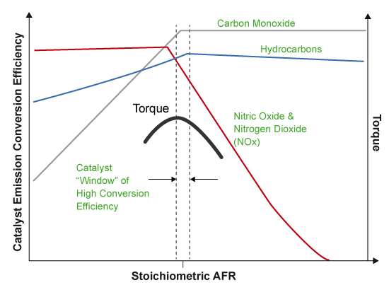
While producing torque, the engine must comply with emission standards. To meet the tailpipe emission standards, the ECU operates a three-way-catalyst (TWC) at the stoichiometric air-fuel ratio (AFR).
In addition to emission controls, the ECU:
Maximizes torque at middle speeds and high loads by operating rich of stoichiometry.
Limits piston crown temperature at high speeds and high loads by running rich of stoichiometry.
Air Mass Flow Models
To calculate engine air mass flow, configure the SI engine to use either of these air mass flow models.
| Air Mass Flow Model | Description |
|---|---|
| SI Engine Speed-Density Air Mass Flow Model |
Uses the speed-density equation to calculate the engine air mass flow, relating the engine air mass flow to the intake manifold pressure and engine speed. Consider using this air mass flow model in engines with fixed valvetrain designs. |
| SI Engine Dual-Independent Cam Phaser Air Mass Flow Model |
To calculate the engine air mass flow, the dual-independent cam phaser model uses:
In contrast to typical embedded air mass flow calculations based on direct air mass flow measurement with an air mass flow (MAF) sensor, this air mass flow model offers:
|
Torque Models
To calculate the brake torque, configure the SI engine to use either of these torque models.
| Brake Torque Model | Description |
|---|---|
| SI Engine Torque Structure Model | For the structured brake torque calculation, the SI engine uses tables for the inner torque, friction torque, optimal spark, spark efficiency, and lambda efficiency. If you select Crank angle pressure and torque on the block Torque tab, you can:
|
| SI Engine Simple Torque Model |
For the simple brake torque calculation, the SI engine block uses a torque lookup table map that is a function of engine speed and load. |
See Also
SI Controller | SI Core Engine