Measurements Service Interface Properties
R2026b
Use the Measurements tab of the Service Mappings editor to map signals of Out Bus Element blocks, block states, and block data stores
Properties
Use this tab of the Service Mappings editor to map measurable model elements to measurement service interface definitions. In the spreadsheet, there are 3 parent entries that correspond to the 3 types of measurable model elements. Each parent entry has a one-level collapsible child entry set. Each child entry corresponds to a measurable model element of the parent entry type. These are the 3 parent entries:
Local Data Stores — Use this section to configure the properties of measurement service interfaces for data stores defined in the model. To learn about local data store, see Data Stores in Generated Code (Embedded Coder).
Signals — Use this section to select which model signals to measure and to configure the measuring service interface properties for the measured signals. Root-level signals cannot be configured for code generation in this tab. To configure root-level signals, use the Receivers tab of the Service Mappings editor. To learn about model signals, see Configure Signal Data for C Code Generation (Embedded Coder).
States — Use this section to configure the properties of measurement service interfaces of states in model blocks. States are block parameters whose value in the current step of the model needs to be remembered and used in future step, such as the value of a Unit Delay block. To learn about model states, see Configure Block States for C Code Generation (Embedded Coder).
This property is read-only.
Name of the model element that corresponds to the table entry.
Code
Use the Code section to configure the variables, in the generated model code, that correspond to the measurable model elements you map to service interface definitions.
Determines whether the generated code allows measuring of the corresponding model element. From the list, selected one of these:
MeasuredThe generated code allows measuring of the corresponding model element.
Not measuredThe generated code does not allow measuring of the corresponding model element.
Default:MeasuredorDefault:Not measuredUse the predefined default value,
MeasuredorNot measured, to determine whether the generated code allows measuring of the corresponding model element. Select this option for model elements that need to use the predefined value regardless of its value, for example, when you need your model behavior to be consistent with other models.Persistency(only supported for Local Data Stores and States)The generated code allows measuring of the corresponding model element, and the data is preserved in non-volatile memory. For more information about persistent memory in AUTOSAR Adaptive, see Model AUTOSAR Adaptive Persistent Memory.
Read only. The path of the containing system of the model element, relative to the
top model. For example, if the model element is a block in the top model, then the
value of Path is the name of the top model.
Only applicable when you select Default:Measured,
Measured or Persistency as the
Measurement Service. In the generated code, the
identifier of the variable that corresponds to the measurable model element, specified
as a text scalar. If you leave the Identifier property empty, the
identifier of the variable is the name of the model element.
Access this property from the Property Inspector or from the dialog
box for additional properties. To open the dialog box, click the pencil icon
 at the end of the table entry that corresponds to the model
element whose service interface you need to configure.
at the end of the table entry that corresponds to the model
element whose service interface you need to configure.
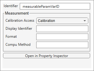
Measurement
Use the Measurement section to configure properties that are used for generating the ASAP2 file. To read more about generated ASAP2 files, see:
Introduction to ASAP2 File (Embedded Coder)
Configure Model Data Elements for ASAP2 File Generation (Embedded Coder)
Access the measurement properties from the Property Inspector or
from the dialog box for additional properties. To open the dialog box, click the pencil icon
at the end of the table entry that corresponds to the model element
whose service interface you need to configure.

The calibration type for the parameter in the ASAP2 file. From the list, select one of these:
Calibration(default)Allow the calibration of the corresponding variable in the calibration tool.
NoCalibrationDo not allow the calibration of the corresponding variable in the calibration tool.
Optional property for the name of the corresponding variable in calibration tool, as indicated in the ASAP2 file. Specified as a text scalar.
The format to use for displaying the corresponding variable in calibration tool,
as indicated in the ASAP2 file, specified as
%,
where length.layoutlength and layout are
integers. Leave the Format property empty to have the calibration
tool use the format of the Compu Method with the corresponding variable.
Conversion method name in the ASAP2 file, specified as a text scalar. The method
is used for converting the ECU-internal value to a physical value for easy
readability. Leave the Compu Method property empty to have the
calibration tool use the default method with the corresponding variable.
More About
Model signals are not automatically added to the mappings of the model. To add a signal, select it, and do one of the following:
Click on the add signal button
 on the upper left corner of the Service Mappings
editor.
on the upper left corner of the Service Mappings
editor.Touch the ellipsis above the signal line in the model canvas
 to open the signal buttons. Then click on the add signal button
 .
.
This snapshot shows the two alternative add signal buttons:
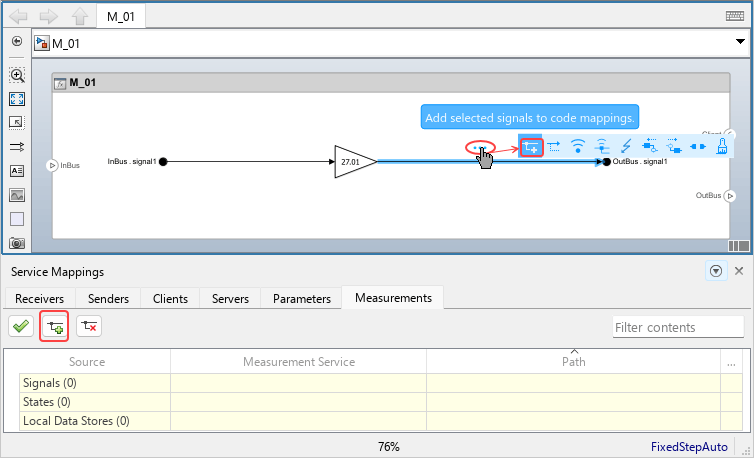
After you add the signal, it appears in the spreadsheet under the Signals parent entry, and it is labeled as configured for code generation.

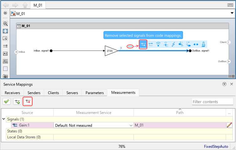
To remove a signal that you previously added to the Service Mappings editor, select the signal in the model canvas, or the corresponding entry in the spreadsheet, and do one of these:
Click on the remove button
 on the upper left corner of the Service Mappings
editor.
on the upper left corner of the Service Mappings
editor.Touch the ellipsis above the signal line in the model canvas
 to open the signal buttons. Then click on the remove signal
button
to open the signal buttons. Then click on the remove signal
button  .
.
This snapshot shows the two alternative remove signal buttons:
Version History
Introduced in R2026b
See Also
Parameters Service Interface Properties (Embedded Coder) | Service Mappings Editor | Generate Calibration Files (Embedded Coder) | Property Inspector
Topics
- Introduction to ASAP2 File (Embedded Coder)
- Configure Model Signals, States, and Data Stores with Measurement Service Interface Definitions (Embedded Coder)
- Data Stores in Generated Code (Embedded Coder)

