Configure AUTOSAR Adaptive Elements and Properties
In Simulink®, you can use the AUTOSAR Dictionary and the Code Mappings editor separately or together to graphically configure an AUTOSAR adaptive software component and map Simulink model elements to AUTOSAR component elements. For more information, see AUTOSAR Component Configuration.
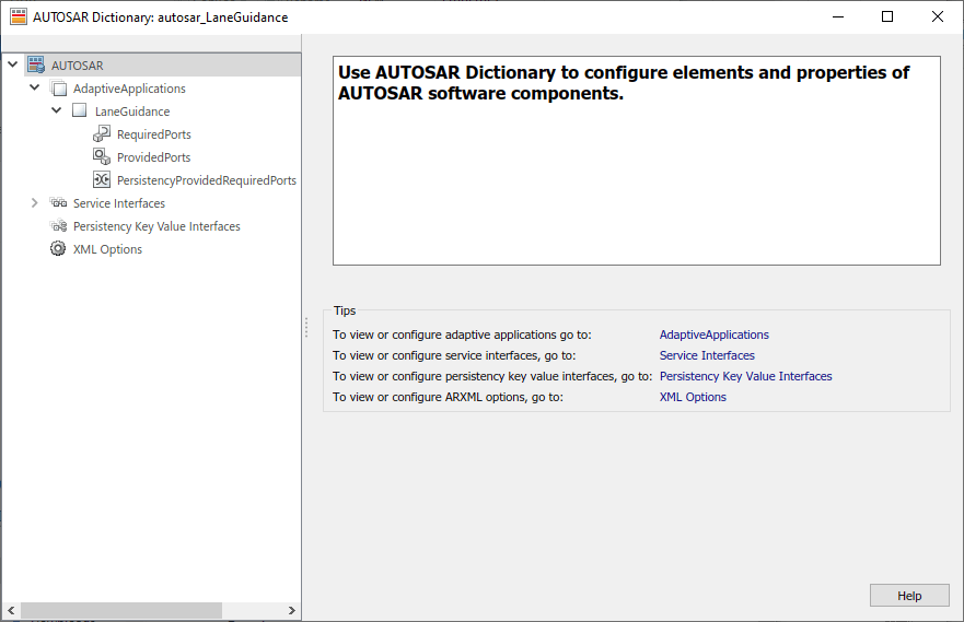
Use the AUTOSAR Dictionary to configure AUTOSAR elements from an AUTOSAR perspective. Using a tree format, the AUTOSAR Dictionary displays a mapped AUTOSAR adaptive component and its elements, communication interfaces, and XML options. Use the tree to select AUTOSAR elements and configure their properties. The properties that you modify are reflected in exported ARXML descriptions and potentially in generated AUTOSAR-compliant C++ code.
AUTOSAR Elements Configuration Workflow
To configure AUTOSAR component elements for the Adaptive Platform in Simulink:
Open a model for which the AUTOSAR system target file
autosar_adaptive.tlcis selected.Create or open a mapped view of the AUTOSAR model. In the model window, do one of the following:
From the Apps tab, open the AUTOSAR Component Designer app.
Click the perspective control in the lower-right corner and select Code.
If the model has not yet been mapped to an AUTOSAR software component, the AUTOSAR Component Quick Start opens. Work through the quick-start procedure and click Finish. For more information, see Create Mapped AUTOSAR Component with Quick Start.
The model opens in the AUTOSAR Code perspective. This perspective displays the model and directly below the model, the Code Mappings editor.
Open the AUTOSAR Dictionary. Either click the AUTOSAR Dictionary button
 in the Code Mappings editor or, on the
AUTOSAR tab, select Code Interface > AUTOSAR Dictionary.
in the Code Mappings editor or, on the
AUTOSAR tab, select Code Interface > AUTOSAR Dictionary.To configure AUTOSAR elements and properties, navigate the AUTOSAR Dictionary tree. You can add elements, remove elements, or select elements to view and modify their properties. Use the Filter Contents field (where available) to selectively display some elements, while omitting others, in the current view.
After configuring AUTOSAR adaptive elements and properties, open the Code Mappings editor. Use Code Mapping tabs to map Simulink elements to new or modified AUTOSAR elements.
To validate the AUTOSAR component configuration, click the Validate button
 . If errors are reported, address them,
and then retry validation.
. If errors are reported, address them,
and then retry validation.
Configure AUTOSAR Adaptive Software Components
AUTOSAR adaptive software components contain AUTOSAR elements defined in the AUTOSAR standard, such as required ports and provided ports. In the AUTOSAR Dictionary, component elements appear in a tree format under the component that owns them. To access component elements and their properties, expand the component name.
To configure AUTOSAR adaptive software component elements and properties:
Open a model for which a mapped AUTOSAR adaptive software component has been created. For more information, see Component Creation.
From the Apps tab, open the AUTOSAR Component Designer app.
Open the AUTOSAR Dictionary. Either click the AUTOSAR Dictionary button
in the Code Mappings editor or, on the
AUTOSAR tab, select Code Interface > AUTOSAR Dictionary.In the leftmost pane of the AUTOSAR Dictionary, under AUTOSAR, select AdaptiveApplications.
The adaptive applications view in the AUTOSAR Dictionary displays adaptive software components. You can rename an AUTOSAR adaptive component by editing its name text.

In the leftmost pane of the AUTOSAR Dictionary, expand AdaptiveApplications and select an AUTOSAR adaptive component.
The component view in the AUTOSAR Dictionary displays the name and type of the selected component, and component options for ARXML file export. You can modify the AUTOSAR package to be generated for the component.
To specify the AUTOSAR package path, you can do either of the following:
Enter a package path in the Package parameter field. Package paths can use an organizational naming pattern, such as
/CompanyName/Powertrain.To open the AUTOSAR Package Browser, click the button to the right of the Package field. Use the browser to navigate to an existing package or create a package. When you select a package in the browser and click Apply, the component Package parameter value is updated with your selection. For more information about the AUTOSAR Package Browser, see Configure AUTOSAR Package for Component, Interface, CompuMethod, or SwAddrMethod.
For more information about component XML options, see Configure AUTOSAR Packages.

Configure AUTOSAR Adaptive Service Interfaces and Ports
An AUTOSAR adaptive software component uses communication interfaces and ports defined in the AUTOSAR standard, like adaptive service interfaces, required ports, and provided ports. In the AUTOSAR Dictionary, communication interfaces appear in a tree format.
To access mapped interfaces and properties of the adaptive service interface, expand the Service Interfaces node and select an interface.
To access required and provided ports and their properties, expand an application node and select either RequiredPorts or ProvidedPorts.
The interface and port views in the AUTOSAR Dictionary support modeling AUTOSAR adaptive service communication in Simulink. You can use the AUTOSAR Dictionary to first configure AUTOSAR service interfaces, events, and C++ namespaces, and then configure required and provided ports. For more information, see Model AUTOSAR Adaptive Service Communication.
You can also define individual C++ namespaces for data types in the Architectural Data section of a linked data dictionary.
Configure Adaptive AUTOSAR Service Interfaces, Required and Provided Ports in AUTOSAR Dictionary
To configure AUTOSAR Adaptive Service Interfaces elements and properties, open a model for which a mapped AUTOSAR adaptive software component has been created and open the AUTOSAR Dictionary.
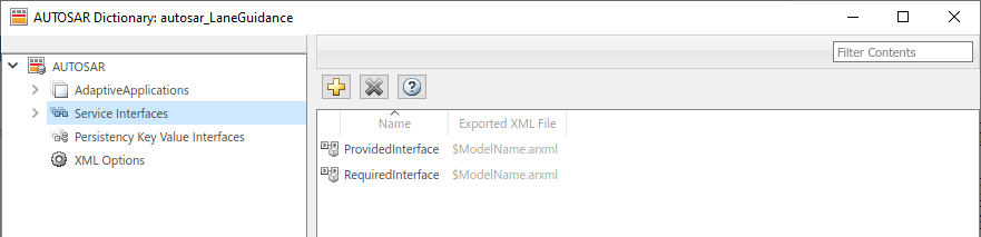
In the leftmost pane of the AUTOSAR Dictionary, select Service Interfaces.
The service interfaces view in the AUTOSAR Dictionary lists AUTOSAR service interfaces and their properties. You can:
Select a service interface and rename it by editing its name text.
To add a service interface, click the Add button
 and use the Add Interfaces dialog
box. Specify an interface name, the number of events it contains,
and the path of the Interface package.
and use the Add Interfaces dialog
box. Specify an interface name, the number of events it contains,
and the path of the Interface package.To remove a service interface, select the interface and then click the Delete button
 .
.
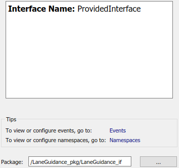
In the leftmost pane of the AUTOSAR Dictionary, expand Service Interfaces and select a service interface from the list.
The service interface view in the AUTOSAR Dictionary displays the name of the selected service interface and the AUTOSAR package to be generated for the interface.
To modify the AUTOSAR package for the interface, you can do either of the following:
Enter a package path in the Package parameter field.
To open the AUTOSAR Package Browser, click the button to the right of the Package field. Use the browser to navigate to an existing package or create a package. When you select a package in the browser and click Apply, the interface Package parameter value is updated with your selection. For more information about the AUTOSAR Package Browser, see Configure AUTOSAR Package for Component, Interface, CompuMethod, or SwAddrMethod.
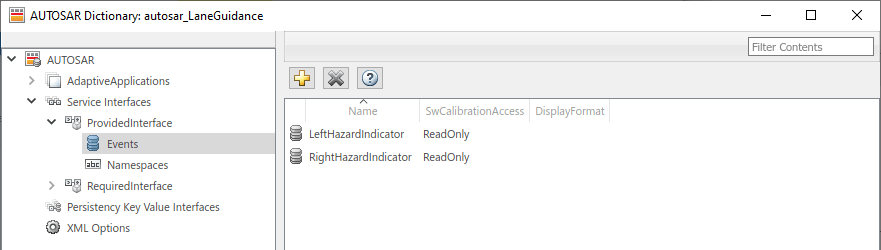
In the leftmost pane of the AUTOSAR Dictionary, expand the selected interface and select Events.
The events view in the AUTOSAR Dictionary lists AUTOSAR service interface events and their properties. You can:
Select a service interface event and edit the name value.
Specify the level of calibration and measurement tool access to service interface events. Select an event and set its SwCalibrationAccess value to
ReadOnly,ReadWrite, orNotAccessible.Optionally specify the format to be used by calibration and measurement tools to display the event. In the DisplayFormat field, enter an ANSI® C
printfformat specifier string. For example,%2.1dspecifies a signed decimal number. The number has a minimum width of two characters and a maximum precision of one digit, producing a displayed value such as 12.2. For more information about constructing a format specifier string, see Configure DisplayFormat.To add an event, click the Add button
.To remove an event, select the event and then click the Delete button
.
In the leftmost pane of the AUTOSAR Dictionary, below Events, select Namespaces.
The namespaces view in the AUTOSAR Dictionary enables you to define a unique namespace for each service interface. The code generator uses the defined namespace when producing C++ code for the interface. To modify or construct a namespace specification, you can:
Select a namespace element and edit the name value.
To add a namespace element to the namespace specification, click the Add button
.To remove a namespace element, select the element and then click the Delete button
.
For example, this namespaces view defines namespace
company::chassis::providedfor service interfaceProvidedInterface.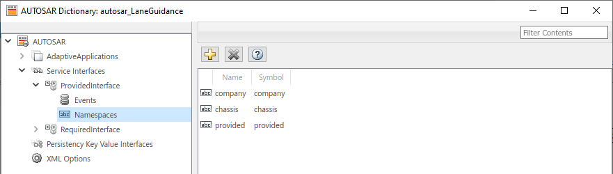
To configure AUTOSAR required and provided port elements, open a model for which a mapped AUTOSAR adaptive software component has been created and open the AUTOSAR Dictionary.
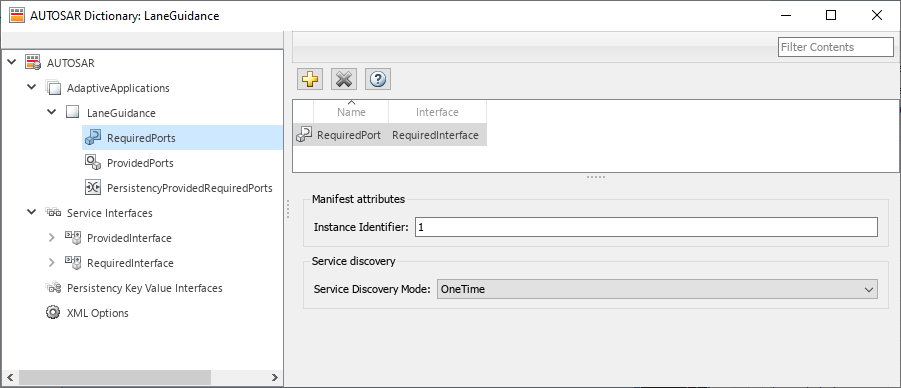
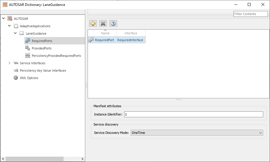
In the leftmost pane of the AUTOSAR Dictionary, expand the component name and select RequiredPorts.
The required ports view in the AUTOSAR Dictionary lists required ports and their properties. You can:
Select an AUTOSAR required port, and view and optionally reselect its associated service interface.
Rename a required port by editing its name text.
To configure adaptive service instance identifier for a required port, select the port and view its Manifest attributes. If Instance Identifier is selected to identify the service instance, examine the value for Instance Identifier. You can enter a value or accept an existing value. For more information, see Configure AUTOSAR Adaptive Service Instance Identifier.
To configure the adaptive service discovery behavior for a required port, select the port and view its Service Discovery Mode. You can select mode
OneTimeorDynamicDiscovery. For more information, see Configure AUTOSAR Adaptive Service Discovery Modes.To add a required port, click the Add button
and use the Add Ports dialog box.
Specify a port name and associate it with an existing service
interface.To remove a required port, select the port and then click the Delete button
.
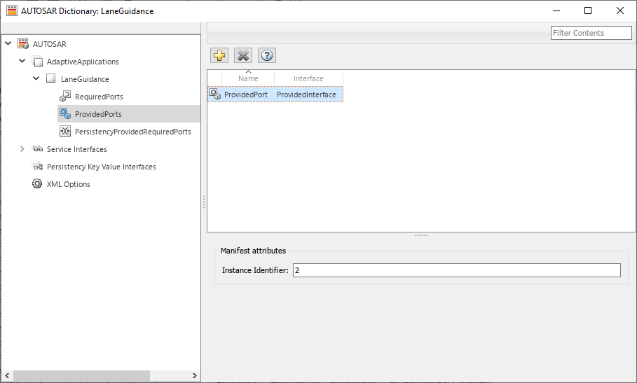
In the leftmost pane of the AUTOSAR Dictionary, select ProvidedPorts.
The provided ports view in the AUTOSAR Dictionary lists provided ports and their properties. You can:
Select an AUTOSAR provided port, and view and optionally reselect its associated service interface.
Rename a provided port by editing its name text.
To configure adaptive service instance identifier for a provided port, select the port and view its Manifest attributes. If Instance Identifier is selected to identify the service instance, examine the value for Instance Identifier. You can enter a value or accept an existing value. For more information, see Configure AUTOSAR Adaptive Service Instance Identifier.
To add a provided port, click the Add button
and use the Add Ports dialog box.
Specify a port name and associate it with an existing service
interface.To remove a provided port, select the port and then click the Delete button
.
To map Simulink root inports and outports to AUTOSAR required and provided service ports and service interface events, see Map Inports and Outports to AUTOSAR Service Ports and Events.
Generate C++ Code with Individual C++ Namespaces for Architectural Data Types Consumed in AUTOSAR Adaptive Platform Models
For component models configured for the AUTOSAR Adaptive Platform, generate C++ code with individual C++ namespaces for architectural data types and export the individual C++ namespaces as namespace symbols in exported ARXML files. To generate and export the individual C++ namespaces of data types, you configure the C++ Namespace code generation property of data types defined in the Architectural Data section of a linked data dictionary.
To configure individual C++ namespaces of data types defined in the Architectural Data section of a data dictionary:
Open the Architectural Data Editor and create a new data dictionary by selecting the New in the File section of the editor toolstrip. Name the data dictionary
ArchDataTypes.In the Architectural Data Editor, in the Create section of the toolstrip, add an alias data type to the data dictionary by selecting Alias Type.
Select the alias data type, and expand the Code Generation section in the Details pane.
Specify the Header file as
impl_type_aliastype.h.Specify the C++ Namespace as
alias::ns.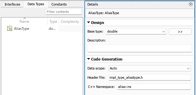
Create a component model configured for the AUTOSAR Adaptive platform. This example uses the Software Component (Adaptive) model template from the Simulink Start Page. For steps to create the model used in this example, see Create Mapped AUTOSAR Component with Simulink Start Page.
On the Modeling tab, expand the Design section and click Link to Data Dictionary. In the Model Properties dialog box, browse for and select the
ArchDataTypesdata dictionary file. Click Apply, and then click OK.In the model canvas, double-click the
RequiredPort.In1port to open the input port properties dialog box.Click (Data mode: message) next to the
In1port. The Attributes of 'RequiredPort.In1' dialog box opens. SelectAliasTypefrom the Data type list.
Save the model and data dictionary. Export ARXML and generate C++ code.
Inspect the generated C++ code.
Header file
impl_types_aliastype.hdefines the architectural alias data type including the assigned C++ namespacealias::ns.#ifndef ALIAS_NS_IMPL_TYPE_ALIASTYPE_H_ #define ALIAS_NS_IMPL_TYPE_ALIASTYPE_H_ #include <cstdint> namespace alias { namespace ns { using AliasType = double; } /* namespace ns */ } /* namespace alias */ #endif //ALIAS_NS_IMPL_TYPE_ALIASTYPE_H_In the exported ARXML file
modelname_datatype.arxmlNAMESPACEStagging.... <ELEMENTS> <STD-CPP-IMPLEMENTATION-DATA-TYPE UUID="..."> <SHORT-NAME>AliasType</SHORT-NAME> <CATEGORY>TYPE_REFERENCE</CATEGORY> <NAMESPACES> <SYMBOL-PROPS> <SHORT-NAME>alias</SHORT-NAME> <SYMBOL>alias</SYMBOL> </SYMBOL-PROPS> <SYMBOL-PROPS> <SHORT-NAME>ns</SHORT-NAME> <SYMBOL>ns</SYMBOL> </SYMBOL-PROPS> </NAMESPACES> <TEMPLATE-ARGUMENTS> <CPP-TEMPLATE-ARGUMENT> <TEMPLATE-TYPE-REF DEST="STD-CPP-IMPLEMENTATION-DATA-TYPE">/DataTypes/SwBaseTypes/double</TEMPLATE-TYPE-REF> </CPP-TEMPLATE-ARGUMENT> </TEMPLATE-ARGUMENTS> </STD-CPP-IMPLEMENTATION-DATA-TYPE> </ELEMENTS> ...
Configure AUTOSAR Adaptive Persistent Memory Interfaces and Ports
An AUTOSAR adaptive software component uses communication interfaces and ports defined in the AUTOSAR standard, including adaptive persistency key value interfaces and persistency provided-required ports. In the AUTOSAR Dictionary, interfaces and ports appear in a tree format.
To access persistent memory interfaces and their properties, expand the Persistency Key Value Interfaces node and select an interface.
To access persistent memory ports and their properties, expand an application node and select PersistencyProvidedRequiredPorts.
The interface and port views in the AUTOSAR Dictionary support modeling AUTOSAR adaptive persistent memory in Simulink. You use the AUTOSAR Dictionary to first configure AUTOSAR persistency key value interfaces and data elements, and then configure persistency provided-required ports. For more information, see Model AUTOSAR Adaptive Persistent Memory.
To configure AUTOSAR adaptive persistency key value interfaces, open a model for which a mapped AUTOSAR adaptive software component has been created and open the AUTOSAR Dictionary.
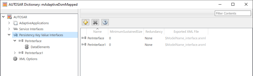
In the leftmost pane of the AUTOSAR Dictionary, select Persistency Key Value Interfaces.
This view in the AUTOSAR Dictionary lists AUTOSAR persistency key value interfaces and their properties. You can:
Select a persistency interface and rename it by editing its name text.
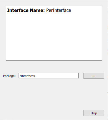
To add a persistency interface, click the Add button
and use the Add Interfaces
dialog box. Specify an interface name, the number of data
elements it contains, and the path of the Interface
package.To remove a persistency interface, select the interface and then click the Delete button
.
In the leftmost pane of the AUTOSAR Dictionary, expand Persistency Key Value Interfaces and select a persistency interface from the list.
The persistency interface view in the AUTOSAR Dictionary displays the name of the selected persistency interface and the AUTOSAR package to be generated for the interface.
To modify the AUTOSAR package for the interface, you can do either of the following:
Enter a package path in the Package parameter field.
To open the AUTOSAR Package Browser, click the button to the right of the Package field. Use the browser to navigate to an existing package or create a package. When you select a package in the browser and click Apply, the interface Package parameter value is updated with your selection. For more information about the AUTOSAR Package Browser, see Configure AUTOSAR Package for Component, Interface, CompuMethod, or SwAddrMethod.
In the leftmost pane of the AUTOSAR Dictionary, expand the selected interface and select DataElements.
The data elements view in the AUTOSAR Dictionary lists AUTOSAR persistency interface data elements and their properties. You can:
Select a persistency interface data element and edit the name value.
To add a data element, click the Add button
.To remove a data element, select the data element and then click the Delete button
.
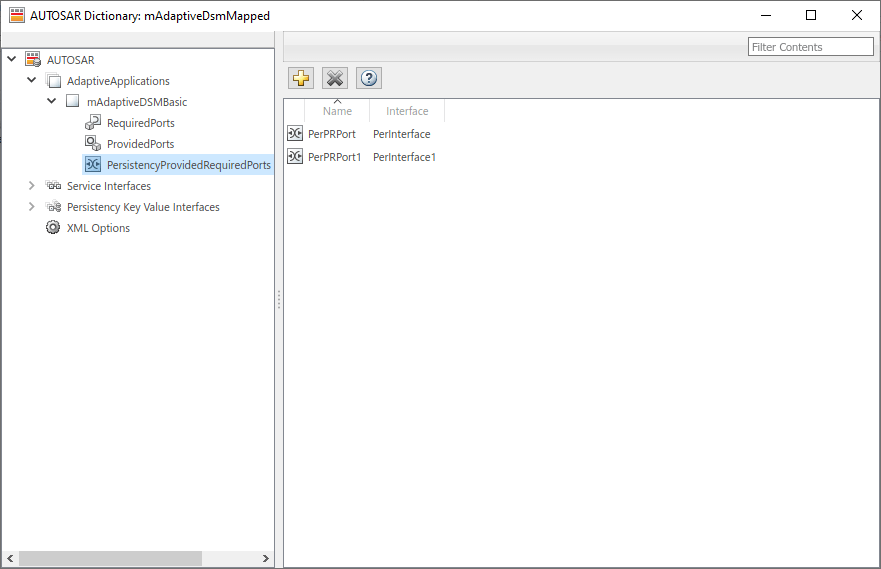
To configure AUTOSAR adaptive persistency provided-required port elements, open a model for which a mapped AUTOSAR adaptive software component has been created and open the AUTOSAR Dictionary.
In the leftmost pane of the AUTOSAR Dictionary, select PersistencyProvidedRequiredPorts. This view in the AUTOSAR Dictionary lists AUTOSAR persistency provided-required ports and their properties. You can:
Select an AUTOSAR persistency provided-required port and select or modify its associated persistency key value interface.
Rename a persistency port by editing its name text.
To add a persistency port, click the Add button
and use the Add Ports dialog box. Specify
a port name and associate it with an existing persistency key value
interface.To remove a persistency port, select the port and then click the Delete button
.
To map Simulink data stores to AUTOSAR persistency provided-required ports and key value interface data elements, see Map Data Stores to AUTOSAR Persistent Memory Ports and Data Elements.
Configure AUTOSAR Adaptive XML Options
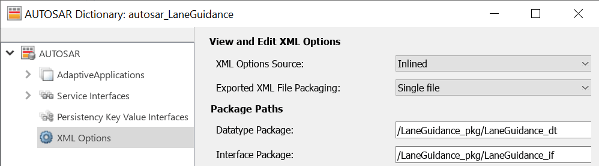
To configure AUTOSAR adaptive XML options for ARXML export, open a model for which a mapped AUTOSAR adaptive software component has been created and open the AUTOSAR Dictionary. Select XML Options.
The XML options view in the AUTOSAR Dictionary displays XML export parameters and their values. You can configure:
XML file packaging for AUTOSAR elements created in Simulink
AUTOSAR package paths
Aspects of exported AUTOSAR XML content
Exported XML File Packaging
In the XML options view, you can specify the granularity of XML file packaging for AUTOSAR elements created in Simulink. Imported AUTOSAR XML files retain their file structure, as described in Round-Trip Preservation of AUTOSAR XML File Structure and Element Information. Select one of the following values for Exported XML file packaging.
Single file— Exports XML into a single file,modelname.arxmlModular— Exports XML into multiple files, named according to the type of information contained.Exported File Name File Contents modelname_component.arxmlAdaptive software components, including required and provided ports.
This file is the main ARXML file exported for the Simulink model. In addition to software components, the component file contains packageable elements that the exporter does not move to data type or interface files based on AUTOSAR element category.
modelname_datatype.arxmlData types and related elements, including:
Application data types
Standard Cpp implementation data types
Constant specifications
Physical data constraints
Units and unit groups
Software record layouts
modelname_interface.arxmlAdaptive interfaces, including required and provided service interfaces with namespaces and events.
Alternatively, you can programmatically configure exported XML file packaging
by calling the AUTOSAR set function. For property
ArxmlFilePackaging, specify either
SingleFile or Modular. For
example:
arProps = autosar.api.getAUTOSARProperties(hModel);
set(arProps,'XmlOptions','ArxmlFilePackaging','SingleFile');
For the Adaptive Platform, model builds also generate XML manifests for AUTOSAR executables and service instances. For more information, see Generate AUTOSAR Adaptive C++ and XML Files.
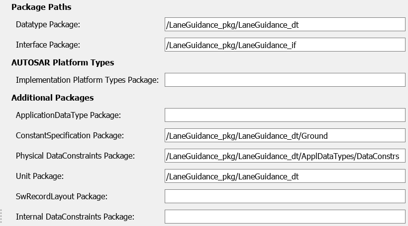
AUTOSAR Package Paths
In the XML options view, you can configure AUTOSAR packages (AR-PACKAGEs), which contain groups of AUTOSAR elements and reside in a hierarchical AR-PACKAGE structure. The AR-PACKAGE structure for a component is logically distinct from the ARXML file partitioning selected with the XML option Exported XML file packaging or imported from AUTOSAR XML files. For more information about AUTOSAR packages, see Configure AUTOSAR Packages.
Inspect and modify the AUTOSAR package paths grouped under the headings Package Paths and Additional Packages.
Alternatively, you can programmatically configure an AUTOSAR package path by
calling the AUTOSAR set function. Specify a package
property name and a package path. For example:
arProps = autosar.api.getAUTOSARProperties(hModel);
set(arProps,'XmlOptions','ApplicationDataTypePackage',...
    '/Company/Powertrain/DataTypes/ApplDataTypes');
For more information about AUTOSAR package property names and defaults, see Configure AUTOSAR Packages and Paths.
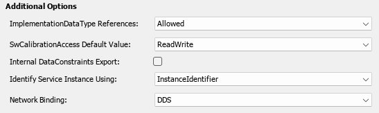
Additional XML Options
In the XML options view, under the heading Additional Options, you can configure aspects of exported AUTOSAR XML content.
You can:
Optionally override the default behavior for generating AUTOSAR application data types in ARXML code. To force generation of an application data type for each AUTOSAR data type, change the value of ImplementationDataType Reference from
AllowedtoNotAllowed. For more information, see Control Application Data Type Generation.Control the default value of the SwCalibrationAccess property of generated AUTOSAR measurement variables, calibration parameters, and signal and parameter data objects. For SwCalibrationAccess DefaultValue, select one of the following values:
ReadOnly— Read access only.ReadWrite(default) — Read and write access.NotAccessible— Not accessible with calibration and measurement tools.
For more information, see Configure SwCalibrationAccess.
Optionally override the default behavior for generating internal data constraint information for AUTOSAR implementation data types in ARXML code. To force export of internal data constraints for implementation data types, select the option Internal DataConstraints Export. For more information, see Configure AUTOSAR Internal Data Constraints for Export.
Specify the form in which to generate adaptive service instance information. Set Identify Service Instance Using to
InstanceIdentifierorInstanceSpecifier. The form that you select is used to identify service instances in generated Proxy and Skeleton functions. For more information, see Configure AUTOSAR Adaptive Service Instance Identifier.Specify the network binding option through which the AUTOSAR adaptive applications communicate with each other. Set the option to
DDSorSOME/IP.
Alternatively, you can programmatically configure the additional XML options
by calling the AUTOSAR set function. Specify a property
name and value. The valid property names are
ImplementationTypeReference,
SwCalibrationAccessDefault,
InternalDataConstraintExport,
IdentifyServiceInstance, and
NetworkBinding. For example:
arProps = autosar.api.getAUTOSARProperties(hModel);
set(arProps,'XmlOptions','ImplementationTypeReference','NotAllowed');
set(arProps,'XmlOptions','SwCalibrationAccessDefault','ReadOnly');
set(arProps,'XmlOptions','InternalDataConstraintExport',true);
set(arProps,'XmlOptions','IdentifyServiceInstance','InstanceSpecifier')
set(arProps,'XmlOptions','NetworkBinding','SOME/IP')