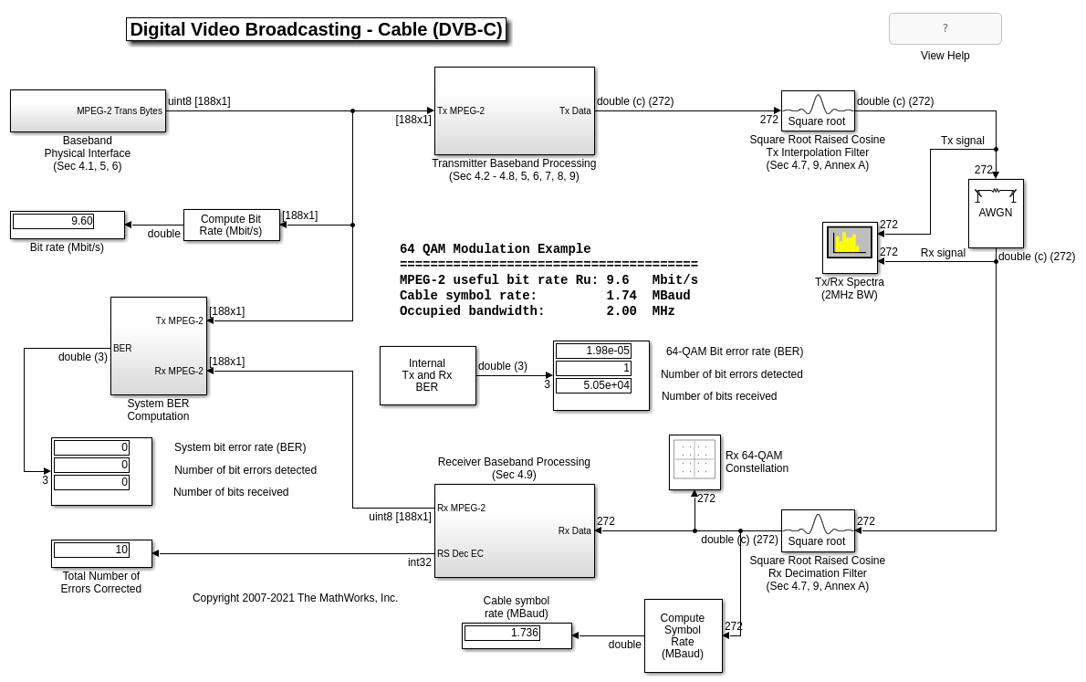
Digital Video Broadcasting - Cable (DVB-C) in Simulink
This model shows part of the ETSI (European Telecommunications Standards Institute) EN 300 429 standard for cable system transmission of digital television signals [ 1 ]. The standard prescribes the transmitter design and sets minimum performance requirements for the receiver.
The purpose of this example is to:
Model the main portions of a possible transmitter design (operating in 64-QAM mode with MPEG-2 Transport Packet data)
Model the main portions of a possible receiver design (operating in 64-QAM mode with MPEG-2 Transport Packet data)
Generate error statistics that will help determine whether the model satisfies the system performance requirements
Illustrate the use of key Communications Toolbox™ library blocks for DVB-C (or similar) system design
Available Example Versions
There are two different versions of this example.
Floating-point version: commdvbc.slx
Fixed-point version: commdvbc_fixpt.slx
Structure of the Example
MATLAB® Workspace Variable Parameter Definitions
When the example model is first loaded, it creates the MATLAB workspace variable prmDVBC, which is a structure with members that are used as parameters in the blocks in the model file. Note also that this workspace variable is cleared when the model is closed.
prmDVBC =

  struct with fields:

             bitsPerByte: 8
             bitsPerMTpl: 6
     MPEG2DatRateBitPerS: 9600000
     rawMPEG2DataPcktLen: 184
     MPEG2TrnsprtPcktLen: 188
    MPEG2TrnsprtFramePer: 1.5667e-04
     MPEG2PcktsPerSprFrm: 8
     MPEG2TrnsSuperFrame: 1504
      PRBSSeqPeriodBytes: 1503
       PRBSSeqPeriodBits: 12024
        RSCodewordLength: 204
       CableChanFrameLen: 272
      CableChanFrmPeriod: 1.5667e-04
      RCosineSampsPerSym: 8
       CableSymbolPeriod: 7.1998e-08
       RCosineFilterSpan: 16
     TxRxSymbolSampDelay: 288
     DeintrlvrAlignDelay: 192
        QAMSymbolMapping: [44 45 41 40 52 54 62 60 46 47 43 … ] (1×64 double)
     ConvIntlNumBranches: 12
       ConvIntlCellDepth: 17
Baseband Physical Interface (Simulated MPEG-2 Data Source)
This portion of the model corresponds to sections 4.1, 5, and 6 in [ 1 ]. The MPEG-2 Transport Packet is defined in ISO®/IEC 13818-1 [ 2 ], and is comprised of 188-byte packets.
Communications Toolbox, DSP System Toolbox™, and Simulink® library blocks are used to simulate a MPEG-2 Transport Packet data stream for system simulation and BER performance measurement purposes.
Transmitter Baseband Processing
Sync1 Inversion and Randomization
This subsystem corresponds to sections 4.2 and 7.1 in [ 1 ]. The MPEG-2 Sync1 byte is inverted, and the data stream (other than the Sync bytes) is randomized for spectrum shaping purposes. A resettable PN Sequence Generator library block is used as part of the scrambler for this data randomization process.
Shortened (204,188) Reed-Solomon Encoder
This library block corresponds to sections 4.3 and 7.2 in [ 1 ]. As described in the standard, this process adds 16 parity bytes to the MPEG-2 Transport Packet to give a (204,188) codeword. This allows up to eight (8) erroneous bytes per transport packet to be corrected by the corresponding receiver Reed-Solomon Decoder block.
Convolutional Interleaver
This library block corresponds to sections 4.4 and 7.3 in [ 1 ]. The interleaving process is based on the Forney approach [ 3 ] and is compatible with the Ramsey type III approach [ 4 ], with I = 12.
Byte (8-bit) to M-Tuple (6-bit) Conversion
A MATLAB® Function block is used to perform this processing. 8-bit data bytes are converted into 64-ary (6-bit) values. This block corresponds to sections 4.5 and 8 in [ 1 ].
Differential Encoding
An example implementation of the Differential Encoding unit as described in sections 4.6 and 8 in [ 1 ] is shown using a MATLAB Function block. For the purposes of this example model, the Differential Encoding unit output is connected to a terminator (i.e., the unit is bypassed).
64-QAM Constellation Mapping
The Rectangular QAM Modulator Baseband library block maps the baseband 64-ary (M-tuple) values to complex (I and Q) 64-QAM constellation symbol values for transmission, as described in sections 4.7 and 9 in [ 1 ].
Square Root Raised Cosine Interpolation Filter
This library block performs the baseband shaping of the complex (I and Q) constellation symbol values for transmission, as described in sections 4.7, 9, and Annex A in [ 1 ].
AWGN Channel
The System FEC as specified by the standard is designed to improve the Bit Error Rate (BER) from 10^-4 to the range, 10^-10 to 10^-11 ("Quasi Error Free" operation). The AWGN Channel library block Signal to Noise Ratio (Eb/No) is set to 16.5 dB corresponding to an operating BER of approximately 10^-4.
Square Root Raised Cosine Rx Decimation Filter
This library block performs the matched decimation filtering of the received complex (I and Q) constellation symbol values, as described in sections 4.7, 9, and Annex A in [ 1 ].
Receiver Baseband Processing
64-QAM Constellation Demapping
The Rectangular QAM Demodulator Baseband library block demaps the received baseband complex (I and Q) 64-QAM constellation symbol values to 64-ary M-tuples, as described in sections 4.7 and 9 in [ 1 ].
Differential Decoding
For the purposes of this example model, the Differential Decoding portion is omitted. Additionally, a more realistic receiver system implementation will likely have equalization and synchronization processing prior to this portion of the receiver model.
M-Tuple (6-bit) to Byte (8-bit) Conversion
A MATLAB Function block is used to perform this processing, which is the inverse of the Byte to M-Tuple processing used in the transmitter. 64-ary (6-bit) M-tuple values are repacked into 8-bit data bytes.
Convolutional Deinterleaver
The Convolutional Deinterleaver library block corresponds to the Convolutional Interleaver library block appearing in the transmitter subsystem implementation. The deinterleaving process is based on the Forney approach [ 3 ] and is compatible with the Ramsey type III approach [ 4 ], with I = 12.
For the sake of example model simplicity, a simple extra delay is used to synchronize the first sync byte into the "0" branch of the Convolutional Deinterleaver. A more realistic receiver system implementation will likely have additional upstream synchronization processing prior to this portion of the model.
Shortened (204,188) Reed-Solomon Decoder
This library block performs the R-S decoding corresponding to the encoded data packets.
Sync1 Inversion and Energy Dispersal Removal
This subsystem performs data descrambling to obtain the received MPEG-2 Transport Packet data bytes.
Results and Displays
To examine the performance of the example, use the included visualization blocks, as listed below.
Overall System Results and Displays:
Bit rate (Mbit/s)displayCable symbol rate (MBaud)display64-QAM bit error rate (BER)displaySystem bit error rate (BER)displayVarious internal bit error rate (BER) displays (under the
Internal Tx and Rx BERsubsystem)
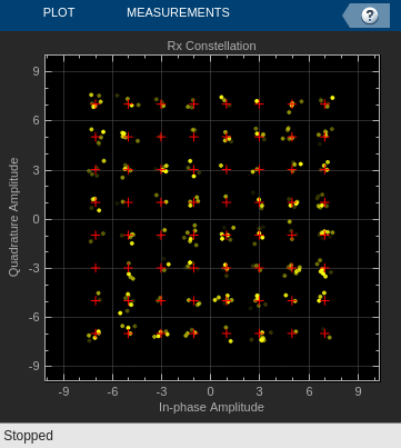
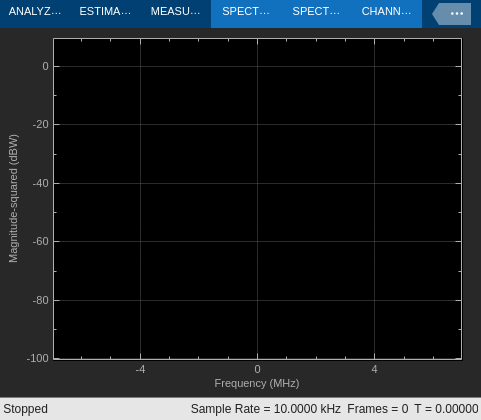
Transmitter/Receiver Results and Displays:
Rx 64-QAM Constellationscatter plotTx/Rx Spectrum (2MHz BW)scopeTotal Number of Errors Correcteddisplay
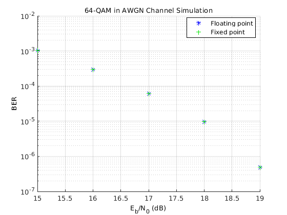
Differences Between the Fixed-Point and Floating-Point Example Versions
There are two different versions of this example -- a floating-point version and a fixed-point version. The examples are similar. In particular, most of the Transmitter Baseband Processing and Receiver Baseband Processing subsystems are identical, and mainly use unsigned integer data types in their signal paths.
The differences between the two versions are in how the signals are processed by the Byte to M-tuple Conversion, 64-QAM Constellation Mapping, Square Root Raised Cosine Tx Interpolation Filter, Square Root Raised Cosine Rx Decimation Filter, 64-QAM Constellation Demapping, and M-Tuple to Byte Conversion blocks. These blocks use floating-point (and built-in integer) arithmetic when their input and/or output signals are floating-point (i.e., data type double or single) or purely built-in integer (e.g., uint8), as is the case in the floating-point version (commdvbc.slx).
In the fixed-point version (commdvbc_fixpt.slx') however, these blocks use fixed-point arithmetic because their input and/or output signals are fixed-point data types (i.e., sfix or ufix in Simulink). Also note that a Fixed-Point Designer™ license is required to run the fixed-point version of the example.
The following simulation results show matching BER performance for the chosen settings when comparing the floating-point version with the fixed-point version.
Selected Bibliography
ETSI Standard EN 300 429 V1.2.1: Digital Video Broadcasting (DVB); Framing structure, channel coding and modulation for cable systems, European Telecommunications Standards Institute, Valbonne, France, 1998.
ISO/IEC 13818-1, "Coding of moving pictures and associated audio."
Forney, G., D., Jr. "Burst-Correcting Codes for the Classic Bursty Channel." IEEE Transactions on Communications, vol. COM-19, October 1971, pp. 772-781.
Ramsey, J. L. "Realization of Optimum Interleavers." IEEE Transactions on Information Theory, IT-16 (3), May 1970, pp. 338-345.