DVB-S.2 Link, Including LDPC Coding
This example shows the application of low density parity check (LDPC) codes in the second generation Digital Video Broadcasting standard (DVB-S.2), which is deployed by DIRECTV in the United States. The example uses communications System objects to simulate a transmitter-receiver chain that includes LDPC encoding and decoding.
Introduction
The ETSI (European Telecommunications Standards Institute) EN 302 307 standard for Broadcasting, Interactive Services, News Gathering and other broadband satellite applications (DVB-S.2) [ 1 ] uses a state-of-the-art coding scheme to increase the channel capacity. The concatenation of LDPC (Low-Density Parity-Check) and BCH codes is the basis of this coding scheme. LDPC codes, invented by Gallager in his seminal doctoral thesis in 1960, can achieve extremely low error rates near channel capacity by using a low-complexity iterative decoding algorithm [ 2 ]. The outer BCH codes are used to correct sporadic errors made by the LDPC decoder.
The channel codes for DVB-S.2 provide a significant capacity gain over DVB-S under the same transmission conditions. Depending on the transmission mode, DVB-S.2 provides Quasi-Error-Free operation (packet error rate below 10^ -7) at about 0.7 dB to 1 dB from the Shannon limit.
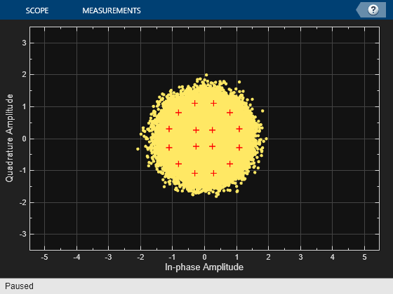
This example simulates the BCH encoder, LDPC encoder, interleaver, modulator, as well as their counterparts in the receiver, according to the DVB-S.2 standard. The example collects the error rate at the demodulator, LDPC decoder, and BCH decoder outputs, determines the distribution of the number of iterations performed by the LDPC decoder, and shows the received symbol constellation. For more information regarding system structure, simplifications, and assumptions used for this example, see the DVB-S.2 Link, Including LDPC Coding in Simulink example.
See the End-to-End DVB-S2 Simulation with RF Impairments and Corrections (Satellite Communications Toolbox) example that uses constant coding and modulation for a single stream DVB-S2 link.
Initialization
The configureDVBS2Demo.m script initializes some simulation parameters and generates a structure, dvb. The fields of this structure are the parameters of the DVB-S.2 system at hand. It also creates the System objects making up the DVB-S.2 system.
subsystemType = '16APSK 2/3'; % Constellation and LDPC code rate
EsNodB        = 9;            % Energy per symbol to noise PSD ratio in dB
numFrames     = 20;           % Number of frames to simulate

% Initialize
configureDVBS2Demo

% Display system parameters
dvb
dvb =

  struct with fields:

                  CodeRate: '2/3'
                    EsNodB: 9
            ModulationType: '16APSK'
         NumBytesPerPacket: 188
          NumBitsPerPacket: 1504
         BCHCodewordLength: 43200
          BCHMessageLength: 43040
          BCHGeneratorPoly: [1 0 1 1 0 0 0 0 0 0 0 0 1 0 1 0 … ] (1×161 double)
          BCHPrimitivePoly: [1 0 0 0 0 0 0 0 0 0 0 1 0 1 1 0 1]
      NumPacketsPerBBFrame: 28
    NumInfoBitsPerCodeword: 42112
                 BitPeriod: 2.3746e-05
        LDPCCodewordLength: 64800
     LDPCParityCheckMatrix: [21600×64800 logical]
         LDPCNumIterations: 50
           InterleaveOrder: [64800×1 double]
             Constellation: [16×1 double]
             SymbolMapping: [12 14 15 13 4 0 8 10 2 6 7 3 11 9 1 5]
               PhaseOffset: [0.7854 0.2618]
             BitsPerSymbol: 4
           ModulationOrder: 16
             SequenceIndex: 2
        NumSymsPerCodeword: 16200
                  NoiseVar: 0.1259
               NoiseVarEst: 0.3227
            RecDelayPreBCH: 43040
The example uses these System objects and functions.
Simulation objects:
enc            - BCH encoder
dec            - BCH decoder
intrlvr        - Block interleaver
deintrlvr      - Block deinterleaver
chan           - AWGN channel
Performance measurement objects:
PER       - Packet error rate calculator
BERLDPC   - LDPC decoder output error rate calculator
BERMod    - Demodulator output error rate calculator
constDiag - Scatter plot of channel output
meanCalc  - Average of the noise variance
Simulation functions:
pskmod        - PSK modulator
pskdemod      - PSK demodulator
dvbsapskmod   - DVBSAPSK modulator
dvbsapskdemod - DVBSAPSK demodulator
ldpcEncode    - LDPC encoder
ldpcDecode    - LDPC decoder
LDPC Encoder and Decoder Configuration Objects
Create LDPC encoder and decoder configuration objects based on the parity check matrix according to Section 5.3.1 of the DVB-S.2 standard [ 1 ].
encldpcCfg = ldpcEncoderConfig(dvb.LDPCParityCheckMatrix);
decldpcCfg = ldpcDecoderConfig(dvb.LDPCParityCheckMatrix);
Stream Processing Loop
This section of the code calls the processing loop for a DVB-S.2 system. The main loop processes the data frame-by-frame, where the system parameter dvb.NumPacketsPerBBFrame determines the number of data packets per BB frame. The first part of the for-loop simulates the system. The simulator encodes each frame using BCH and LDPC encoders as inner and outer codes, respectively. The encoded bits pass through an interleaver. The modulator maps the interleaved bits to symbols from the predefined constellation. The modulated symbols pass through an AWGN channel. The demodulator employs an approximate log-likelihood algorithm to obtain soft bit estimates. The LDPC decoder decodes the deinterleaved soft bit values and generates hard decisions. The BCH decoder works on these hard decisions to create the final estimate of the received frame.
The second part of the for-loop collects performance measurements such as the bit error rate and a scatter plot. It also estimates the received SNR value.
bbFrameTx  = false(encbch.MessageLength,1);
numIterVec = zeros(numFrames,1);
falseVec   = false(dvb.NumPacketsPerBBFrame,1);

for frameCnt=1:numFrames

    % Transmitter, channel, and receiver
    bbFrameTx(1:dvb.NumInfoBitsPerCodeword) = ...
        logical(randi([0 1],dvb.NumInfoBitsPerCodeword,1));

    bchEncOut = encbch(bbFrameTx);
    ldpcEncOut = ldpcEncode(bchEncOut,encldpcCfg);
    intrlvrOut = intrlv(ldpcEncOut,dvb.InterleaveOrder);

    if dvb.ModulationOrder == 4 || dvb.ModulationOrder == 8
        % Configure PSK modulator according to Section 5.4 of [1], which
        % defines custom constellation diagrams.
        modOut = pskmod(intrlvrOut, dvb.ModulationOrder, dvb.PhaseOffset, ...
            dvb.SymbolMapping, InputType="Bit");
    else
        modOut = dvbsapskmod(intrlvrOut,dvb.ModulationOrder,'s2', ...
            dvb.CodeRate,'InputType','bit','UnitAveragePower',true);
    end

    chanOut = chan(modOut);

    if dvb.ModulationOrder == 4 || dvb.ModulationOrder == 8
        % Configure PSK demodulator according to Section 5.4 of [1], which
        % defines custom constellation diagrams.
        demodOut = pskdemod(chanOut, dvb.ModulationOrder, dvb.PhaseOffset, ...
            dvb.SymbolMapping, OutputType="approxllr", NoiseVariance=dvb.NoiseVar);
    else
        demodOut = dvbsapskdemod(chanOut,dvb.ModulationOrder,'s2', ...
            dvb.CodeRate,'OutputType','approxllr','NoiseVar', ...
            dvb.NoiseVar,'UnitAveragePower',true);
    end

    deintrlvrOut = deintrlv(demodOut,dvb.InterleaveOrder);
    % By default, ldpcDecode stops iterating when all parity checks are
    % satisfied, which reduces decoding time
    [ldpcDecOut, numIter] = ldpcDecode(deintrlvrOut,decldpcCfg,dvb.LDPCNumIterations);
    bchDecOut = decbch(ldpcDecOut);
    bbFrameRx = bchDecOut(1:dvb.NumInfoBitsPerCodeword,1);

    % Error statistics
    comparedBits = xor(bbFrameRx,bbFrameTx(1:dvb.NumInfoBitsPerCodeword));
    packetErr    = any(reshape(comparedBits,dvb.NumBitsPerPacket, ...
        dvb.NumPacketsPerBBFrame));
    per = PER(falseVec,packetErr');
    berMod = BERMod(demodOut<0,intrlvrOut);
    berLDPC = BERLDPC(logical(ldpcDecOut),bchEncOut);

    % LDPC decoder iterations
    numIterVec(frameCnt) = numIter;

    % Noise variance estimate
    noiseVar = meanCalc(var(chanOut - modOut));

    % Scatter plot
    constDiag(chanOut);
end

Executing the error rate measurement objects (hPER, hBERMod, and hBERLDPC), outputs a 3-by-1 vector containing updates of the measured error rate value, the number of errors, and the total number of transmissions (packets or bits). Display the BER at the demodulator output, the BER at the LDPC decoder output, and the packet error rate of the end-to-end system together with the measured SNR at the receiver input. While the demodulator output presents an error rate of more than 10%, the LDPC decoder is able to correct all of the errors and provide error free packets.
fprintf('Measured SNR : %1.2f dB\n',10*log10(1/noiseVar))
fprintf('Modulator BER: %1.2e\n',berMod(1))
fprintf('LDPC BER     : %1.2e\n',berLDPC(1))
fprintf('PER          : %1.2e\n',per(1))
Measured SNR : 8.98 dB
Modulator BER: 8.25e-02
LDPC BER     : 0.00e+00
PER          : 0.00e+00
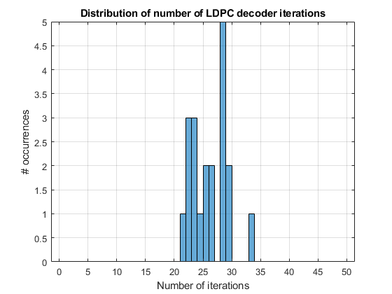
The figure shows the distribution of the number of iterations performed by the LDPC decoder. The decoder was able to decode all the frames without an error before reaching the maximum iteration count of 50.
distFig = figure;
histogram(numIterVec,1:dvb.LDPCNumIterations-1);
xlabel('Number of iterations'); ylabel('# occurrences'); grid on;
title('Distribution of number of LDPC decoder iterations')

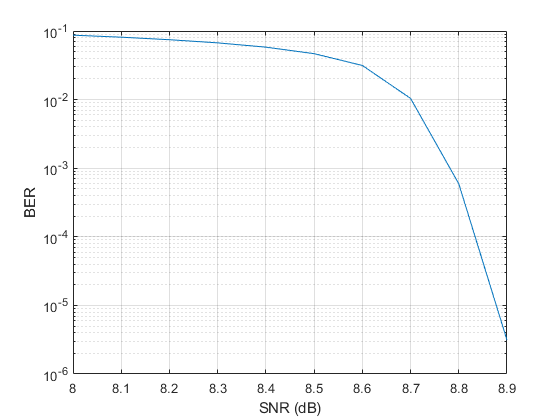
We ran the stream processing loop for 32.4e6 bits for several SNR values. Since this simulation takes a long time, in this example we only provide the result of the simulation stored in a MAT-file.
load berResultsDVBS2Demo.mat cBER_16APSK snrdB_16APSK
berFig = figure;
semilogy(snrdB_16APSK,cBER_16APSK(1,:)); xlim([8 8.9]);
xlabel('SNR (dB)'); ylabel('BER'); grid on

Summary
This example utilized several System objects to simulate part of the DVB-S.2 communication system over an AWGN channel. It showed how to model several parts of the DVB-S.2 system such as the LDPC coding. System performance was measured using the PER and BER values obtained with error rate measurement System objects.
Further Exploration
You can modify parts of this example to experiment with different subsystem types using various values for Es/No and maximum number of LDPC decoder iterations. This example supports the following subsystem types:
     'QPSK 1/4', 'QPSK 1/3', 'QPSK 2/5', 'QPSK 1/2', 'QPSK 3/5', 'QPSK
     2/3', 'QPSK 3/4', 'QPSK 4/5', 'QPSK 5/6', 'QPSK 8/9', 'QPSK 9/10'
'8PSK 3/5', '8PSK 4/5', '8PSK 2/3', '8PSK 3/4', '8PSK 5/6', '8PSK
8/9', '8PSK 9/10' '16APSK 2/3', '16APSK 3/4', '16APSK 4/5', '16APSK 5/6', '16APSK
8/9', '16APSK 9/10' '32APSK 3/4', '32APSK 4/5', '32APSK 5/6', '32APSK 8/9', '32APSK
9/10'Appendix
This example uses the following scripts and helper function:
configureDVBS2Demo.m
getParamsDVBS2Demo.m
createSimObjDVBS2Demo.m
Selected Bibliography
ETSI Standard EN 302 307 V1.1.1: Digital Video Broadcasting (DVB); Second generation framing structure, channel coding and modulation systems for Broadcasting, Interactive Services, News Gathering and other broadband satellite applications (DVB-S2), European Telecommunications Standards Institute, Valbonne, France, 2005-03.
R. G. Gallager, Low-Density Parity-Check Codes, IEEE® Transactions on Information Theory, Vol. 8, No. 1, January 1962, pp. 21-28.
W. E. Ryan, An introduction to LDPC codes, in Coding and Signal Processing for Magnetic Recording Systems (Bane Vasic, ed.), CRC Press, 2004.