FRS/GMRS Walkie-Talkie Receiver
This example shows how to build a walkie-talkie receiver using MATLAB® and Communications Toolbox™. The specific radio standard this example follows is FRS/GMRS (Family Radio Service / General Mobile Radio Service) with CTCSS (Continuous Tone-Coded Squelch System). You can use simulated signals, captured signals, or received signals from a commercial walkie-talkie using the Communications Toolbox Support Package for RTL-SDR Radio.
This example is designed to work with USA standards for FRS/GMRS operation. The technical specifications for these standards can be found in the reference list below. Operation in other countries may or may not work.
Required Hardware and Software
To run this example using captured signals, you need the following software:
To receive signals in real time, you also need the following hardware:
RTL-SDR radio
Walkie-talkie
and the following software
For a full list of Communications Toolbox supported SDR platforms, refer to the "MATLAB and Simulink Hardware Support for SDR" section of Software-Defined Radio (SDR).
Background
Walkie-talkies provide a subscription-free method of communicating over short distances. Although their popularity has been diminished by the rise of cell phones, walkie-talkies are still useful when lack of reception or high per-minute charges hinders cell phone use.
Modern walkie-talkies operate on the FRS/GMRS standards. Both standards use frequency modulation (FM) at 462 or 467 MHz, which is in the UHF (Ultra High Frequency) band.
Run the Example
Click the 'Open Script' button to open and run the example. You need to enter the following information:
Reception duration in seconds
Signal source (simulated signal, captured signal or RTL-SDR radio)
Channel number (1-14)
CTCSS code (1-38, 0 no CTCSS filtering)
Detection threshold for received signal
The example plays the received audio over your computer's speakers.
Receiver Structure
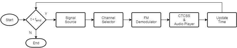
The following block diagram summarizes the receiver code structure. The processing has four main parts: Signal Source, Channel Selector, FM Demodulator, and CTCSS processing.
Signal Source
This example can use three signal sources:
''Simulated Signal'': Simulated FRS/GMRS signal at 240e3 samples/sec
''Captured Signal'': Over-the-air signals written to a file and sourced from a baseband file reader object at 240e3 samples/sec
''RTL-SDR Radio'': RTL-SDR radio at 240e3 samples/sec
If you choose ''RTL-SDR Radio'' as the signal source, this application will search your computer for RTL-SDR radios and ask you to choose one of them as the signal source.
Channel Selector
The receiver removes the DC component and applies a variable gain to the received signal to obtain an approximately known amplitude signal with reduced interference. The receiver then applies a low pass channel separation filter to reduce the signals from adjacent channels. The gap between adjacent channels is 25 kHz, which means the baseband bandwidth is, at most, 12.5 kHz. Thus, we choose the cutoff frequency to be 10 kHz.
Next, a channel selector computes the average power of the filtered signal. If it is greater than a threshold (set to a default of 10%), the channel selector determines that the received signal is from the correct channel and allows the signal to pass through. In the case of an out-of-band signal, although the channel separation filter reduces its magnitude, it is still FM modulated and the modulating signal will be present after FM demodulation. To completely reject such a signal, the channel selector outputs all zeros.
FM Demodulator
This example uses the FM Demodulator Baseband System object™ whose sample rate and maximum frequency deviation are set to 240 kHz and 2.5 kHz, respectively.
CTCSS
First, a decimation filter converts the sampling rate from 240 kHz to 8 kHz. This rate is one of the native sampling rates of your host computer's output audio device. Then, the CTCSS decoder computes the power at each CTCSS tone frequency using the Goertzel algorithm and outputs the code with the largest power. The Goertzel algorithm provides an efficient method to compute the frequency components at predetermined frequencies, that is, the tone code frequencies used by FRS/GMRS.
The script compares the estimated received code with the preselected code. If the two codes match, the signals are passed to the audio device. When the preselected code is zero, it indicates no squelch system is used and the decision block passes the signal at the channel to the audio device no matter which code is used.
Finally, a high pass filter with a cutoff frequency of 260 Hz filters out the CTCSS tones, which have a maximum frequency of 250 Hz. Use an audioDeviceWriter System object™ to play the received signals through your computer's speakers. If you do not hear any sound, select another device using the DeviceName property of the audio device writer object, audioPlayer.
Example Code
The receiver asks for user input and initializes variables. Then it calls the signal source, channel selector, FM demodulator, and CTCSS processor in a loop. The loop also keeps track of the radio time using the frame duration and lost samples reported by the signal source.
The latency output of the signal source is an indication of when the samples were actually received and can be used to determine how close to real time the receiver is running. A latency value of 1 and a lost samples value of 0 indicates that the system is running in real-time. A latency value of greater than one indicates that the receiver was not able to process the samples in real time. Latency is reported in terms of the number of frames. It can be between 1 and 128. If latency is greater than 128, then samples are lost.
% Request user input from the command-line for application parameters
userInput = helperFRSReceiverUserInput;

% Calculate FRS receiver parameters based on the user input
[frsRxParams,sigSrc] = helperFRSReceiverConfig(userInput);

% Create channel selector components
dcBlocker = dsp.DCBlocker('Algorithm', 'Subtract mean');
agc = comm.AGC;
channelFilter = frsRxParams.ChannelFilter;

% Create FM demodulator
fmDemod = comm.FMDemodulator(...
  'SampleRate', frsRxParams.FrontEndSampleRate, ...
  'FrequencyDeviation', frsRxParams.FrequencyDeviation);

% Create CTCSS and audio output components
decimator = dsp.FIRDecimator(...
  frsRxParams.DecimationFactor, ...
  frsRxParams.DecimationNumerator);
decoder = helperFRSCTCSSDecoder( ...
  'MinimumBlockLength', frsRxParams.CTCSSDecodeBlockLength, ...
  'SampleRate', frsRxParams.AudioSampleRate);
audioFilter = frsRxParams.AudioFilter;
audioPlayer = audioDeviceWriter(frsRxParams.AudioSampleRate);

% Initialize radio time
radioTime = 0;

% Main loop
while radioTime < userInput.Duration
  % Receive baseband samples (Signal Source)
  if frsRxParams.isSourceRadio
    [rcv,~,lost,late] = sigSrc();
  else
    rcv = sigSrc();
    lost = 0;
    late = 1;
  end

  % Channel selector
  rcv = dcBlocker(rcv);
  outAGC = agc(rcv);
  outChanFilt = channelFilter(outAGC);
  rxAmp = mean(abs(outChanFilt));
  if rxAmp > frsRxParams.DetectionThreshold
    x = outChanFilt;
  else
    x = complex(single(zeros(frsRxParams.FrontEndSamplesPerFrame, 1)));
  end

  % FM demodulator
  y = fmDemod(x);

  % CTCSS decoder and audio output
  outRC = decimator(y);
  rcvdCode = decoder(outRC);
  if (rcvdCode == frsRxParams.CTCSSCode) || (frsRxParams.CTCSSCode == 0)
    rcvdSig = outRC;
  else
    rcvdSig = single(zeros(frsRxParams.AudioFrameLength, 1));
  end
  audioSig = audioFilter(rcvdSig);
  audioPlayer(audioSig);

  % Update radio time. If there were lost samples, add those too.
  radioTime = radioTime + frsRxParams.FrontEndFrameTime + ...
    double(lost)/frsRxParams.FrontEndSampleRate;
end

% Release the resources
release(fmDemod)
release(audioPlayer)
release(sigSrc)
Further Exploration
The CTCSS decoding computes the DFT (Discrete Fourier Transform) of the incoming signal using the Goertzel algorithm and computes the power at the tone frequencies. Because the tone frequencies are very close to each other (only 3-4 Hz apart) the block length of the DFT should be large enough to provide enough resolution for the frequency analysis. However, long block lengths cause decoding delay. For example, a block length of 16384 will cause 2 seconds of delay because the CTCSS decoder operates at an 8 kHz sampling rate. This creates a trade-off between detection performance and processing latency. The optimal block length may depend on the quality of the transmitter and receiver, the distance between the transmitter and receiver, and other factors. You are encouraged to change the block length in the initialization function by navigating to the helperFRSReceiverConfig function and changing the value of the CTCSSDecodeBlockLength field. This will enable you to observe the trade-off and find the optimal value for your transmitter/receiver pair.
You can explore following functions and System objects for details of the physical layer implementation:
References
Select a Web Site
Choose a web site to get translated content where available and see local events and offers. Based on your location, we recommend that you select: United States.
You can also select a web site from the following list
Americas
- América Latina (Español)
- Canada (English)
- United States (English)
Europe
- Belgium (English)
- Denmark (English)
- Deutschland (Deutsch)
- España (Español)
- Finland (English)
- France (Français)
- Ireland (English)
- Italia (Italiano)
- Luxembourg (English)
- Netherlands (English)
- Norway (English)
- Österreich (Deutsch)
- Portugal (English)
- Sweden (English)
- Switzerland
- United Kingdom (English)
Asia Pacific
- Australia (English)
- India (English)
- New Zealand (English)
- 中国
- 日本Japanese (日本語)
- 한국Korean (한국어)