GSM, CDMA and WiMAX Channel Models
This example shows how to simulate multipath fading channels defined for GSM/EDGE [ 1 2 ], CDMA [ 3 ], and WiMAX [ 4 ] wireless standards. The example uses the Rayleigh and MIMO fading channel System objects™ from Communications Toolbox™ to simulate and visualize the channels.
GSM Channel Model
GSM (Global System for Mobile Communications) is the global standard for 2G mobile communications. The multipath fading channel for GSM was defined in [ 1 2 ] for different communication scenarios including rural area (RAx), hilly terrain (HTx), urban area (TUx). Each scenario was assigned a specific power delay profile (PDP) and Doppler spectrum. In this example, we simulate the hilly terrain scenario (HTx) with 12 taps. We pass GMSK modulated signals through the fading channel and observe its impulse response.
% Set random number generator for repeatability
rng('default');
Create a GMSK modulator using the comm.GMSKModulator object and use it to modulate randomly generated bits. This object is to illustrate that the GMSK modulation is used in the GSM system.
gmskMod = comm.GMSKModulator( ...
    'BitInput', true, ...
    'SamplesPerSymbol', 8);

% Modulate random bits using the GMSK object
x = gmskMod(randi([0 1], 1e4, 1));
Assume mobile speed at 120 km/h. Calculate the Doppler shift at the carrier frequency of 1.8 GHz.
v = 120*1e3/3600;                   % Mobile speed (m/s)
fc = 1.8e9;                         % Carrier frequency
fd = v*fc/physconst('lightspeed');  % Maximum Doppler shift
To simulate the fading channel for HTx, we can configure a comm.RayleighChannel object following the PDP specification in [ 1 2 ]. Alternatively, we can use the stdchan function to create the desired comm.RayleighChannel object, given the scenario input 'gsmHTx12c1'. So we do not have to refer to [ 1 2] for PDP and Doppler spectrum specifications.
Rsym = 270.833e3; % GSM symbol rate
Rsamp = gmskMod.SamplesPerSymbol * Rsym; % GSM sample rate
gsmChan = stdchan('gsmHTx12c1', Rsamp, fd);
We turn on the impulse response visualization for the channel object and send the GMSK modulated data through it. You can observe that the path (tap) delays last over 5 samples. The first 7 and last 5 taps can be grouped into two different clusters. In that sense, the channel characterizes two dominant paths from the transmitter to the receiver with scattering. You can also observe that the impulse response changes reasonably fast at this mobile speed of 120 km/h.
gsmChan.Visualization = 'Impulse response';
gsmChan(x);

CDMA Channel Model
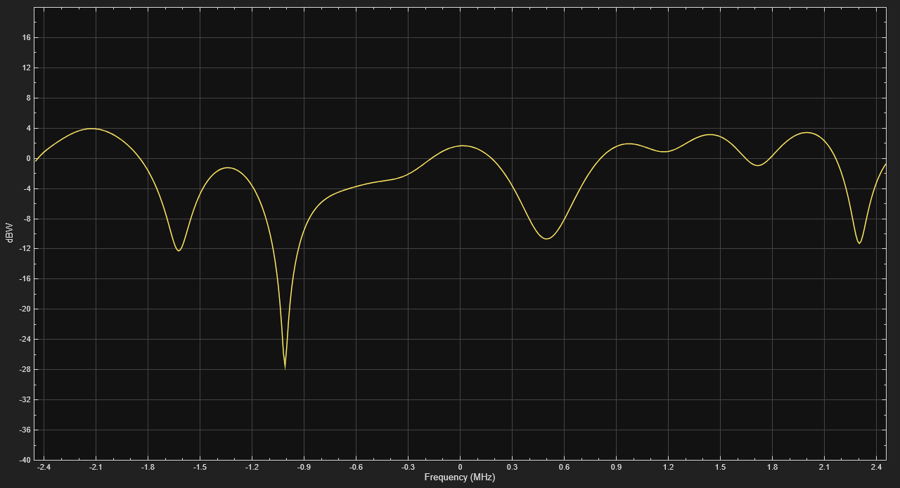
CDMA (Code-Division Multiple Access) is the standard for 3G mobile communications. Like GSM, the multipath fading channel for CDMA was defined in [ 3 ] for different communication scenarios with different PDPs and Doppler spectra. In this example, we simulate the typical urban scenario (TUx) with a low mobile speed and visualize the channel's frequency response. The cdma2000ForwardReferenceChannels and cdma2000ForwardWaveformGenerator functions are used to configure and simulate a CDMA 2000 waveform, which is subsequently transmitted through the fading channel.
% Configure a CDMA waveform and change the packet length
config = cdma2000ForwardReferenceChannels('ALL-RC3');
config.NumChips = 1e4;

% Generate a waveform
waveform = cdma2000ForwardWaveformGenerator(config);
Derive channel sample rate from the waveform configuration. If the SpreadingRate field is 'SR1', it corresponds to a 1.2288 Mcps waveform. If it is 'SR3', it corresponds to a 3.6864 Mcps waveform.
Rsprd = str2double(config.SpreadingRate(3)) * 1.2288e6;
Rsamp = Rsprd * config.OversamplingRatio;

% Assume a human walking speed which is about 5 km/h. Calculate the Doppler
% shift at the carrier frequency of 1.9 GHz.
v = 5*1e3/3600;                     % Mobile speed (m/s)
fc = 1.9e9;                         % Carrier frequency
fd = v*fc/physconst('lightspeed');  % Maximum Doppler shift
Again, configure a CDMA channel for TUx using the stdchan function. Turn on the channel's frequency response visualization and pass the waveform through it. You can observe the obvious frequency-selectivity of the channel. The frequency response varies slowly at this low mobile speed of 5 km/h.
cdmaChan = stdchan('cdmatux', Rsamp, fd);
cdmaChan.Visualization = 'Frequency response';
y = cdmaChan(waveform);
WiMAX Channel Model
The WiMAX (IEEE® 802.16) channel models [ 4 ] for fixed wireless applications are proposed for scenarios where the cell radius is less than 10 km, the directional antennas at the receiver are installed under-the-eaves/windows or on the rooftop, and the base station (BS) antennas are 15 to 40 m in height. The channel models comprise a set of path loss models including shadowing (suburban, urban) and a multipath fading model, which describes the multipath delay profile, the K-factor distribution, and the Doppler spectrum. The antenna gain reduction factor, due to the use of directional antennas, is also characterized.
This example uses a MIMO multipath fading channel System object™ comm.MIMOChannel with two transmit antennas, one receive antenna, and a rounded Doppler spectrum structure. The modified Stanford University Interim (SUI) channel models consist of a set of 6 typical channels used to simulate the IEEE 802.16 channel models (more specifically the 2004 version of the standard for fixed wireless applications). They are proposed for a scenario where: the cell size is 7 km, the BS antenna height is 30 m, the receive antenna height is 6 m, the BS antenna beamwidth is 120 degrees, the receive antenna is either omnidirectional or directional (30 degrees), and only vertical polarization is used.
Each modified SUI channel model has three taps. Each tap is characterized by a relative delay (with respect to the first path delay), a relative power, a Rician K-factor, and a maximum Doppler shift. Two sets of relative powers are specified for each channel model: one for an omnidirectional antenna, and one for a 30 degrees directional antenna. Furthermore, for each set of relative powers, two different K-factors are specified, a K-factor for 90% cell coverage, and a K-factor for 75% cell coverage. Hence, each of the 6 modified SUI channel models comprises parameters for four distinct scenarios. Each modified SUI channel model is further assigned an antenna correlation, defined as the envelope correlation coefficient between signals received at different antenna elements.
The code below constructs a MIMO fading channel System object according to the modified SUI-1 channel model, for an omnidirectional antenna and 90% cell coverage.
The channel model has 3 paths: the first path is Rician while the remaining two are Rayleigh. Each path has a rounded Doppler spectrum for its diffuse component: the parameters are as specified in the doppler('Rounded') structure. While different maximum Doppler shifts are specified for each path in [ 4 ], we use the maximum value of the Doppler shifts for all paths.
We use 2 transmit antennas and 1 receive antenna. Similar to Appendix B of [ 4 ], the correlation coefficient between the two links on each path is taken equal to the antenna spatial correlation. The correlation coefficient is 0.7.
The sample rate for a WiMAX system is 1.429, 2.857, 5.714, 11.429 or 22.857 MHz. At such rates with a small Doppler shift, we need many samples and long simulation time to sufficiently exhibit the channel statistical characteristics. To avoid that, we arbitrarily choose a smaller sample rate of 0.1 MHz. You can increase the sample rate, Rsamp, and number of samples, Ns, at the same time to see the similar statistical results.
Rsamp = 0.1e6;
Ns = 3e6;

wimaxChan = comm.MIMOChannel( ...
    'SampleRate', Rsamp, ...
    'PathDelays', [0 0.4 0.9]*1e-6, ...
    'AveragePathGains', [0 -15 -20], ...
    'FadingDistribution', 'Rician', ...
    'KFactor', 4, ...
    'MaximumDopplerShift', .5, ...
    'DopplerSpectrum', doppler('Rounded'), ...
    'TransmitCorrelationMatrix', [1 0.7; 0.7 1], ...
    'ReceiveCorrelationMatrix', 1, ...
    'PathGainsOutputPort', true);
The code below simulates the modified SUI-1 channel model with a long QPSK modulated frame input.
Nt = size(wimaxChan.TransmitCorrelationMatrix, 1);
x = pskmod(randi([0 3], Ns, Nt), 4);
[~, g] = wimaxChan(x);
The Doppler spectrum of the 1st link of the second path is estimated from the complex path gains and plotted.
figure;
win = hamming(Ns/5);
Noverlap = Ns/10;
pwelch(g(:,2,1),win,Noverlap,[],Rsamp,'centered')
axis([-0.1/10 0.1/10 -80 10]);
legend('Simulation');
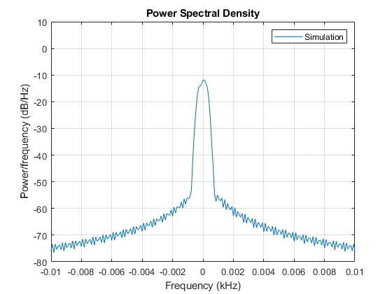
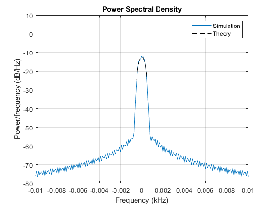
The theoretical rounded Doppler spectrum is overlaid on the estimated Doppler spectrum. We observe a good fit between them.
fd = wimaxChan.MaximumDopplerShift;
f  = -fd:0.01:fd;
a  = wimaxChan.DopplerSpectrum.Polynomial;      % Parameters of the rounded Doppler spectrum
Sd = 1/(2*fd*(a(1)+a(2)/3+a(3)/5))*(a(1)+a(2)*(f/fd).^2+a(3)*(f/fd).^4);
Sd = Sd*10^(wimaxChan.AveragePathGains(2)/10);  % Scaling by average path power

hold on;
plot(f(Sd>0)/1e3,10*log10(Sd(Sd>0)),'k--');
legend('Simulation','Theory');
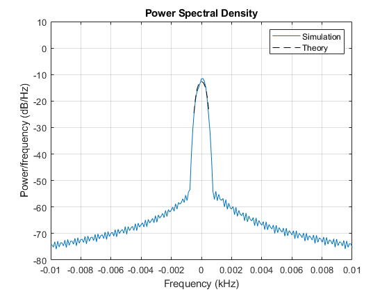
The Doppler spectrum for the 2nd link of the 2nd path is also estimated and compared to the theoretical spectrum. We also observe a good fit between them.
figure;
pwelch(g(:,2,2),win,Noverlap,[],Rsamp,'centered')
axis([-0.1/10 0.1/10 -80 10]);
legend('Simulation');
hold on;
plot(f(Sd>0)/1e3,10*log10(Sd(Sd>0)),'k--');
legend('Simulation','Theory');
For each path, we plot the fading envelope waveforms of both transmit links. We can observe a correlation between the fading envelopes.
figure;
semilogy(abs(g(:,1,1)),'b');
hold on;
grid on;
semilogy(abs(g(:,1,2)),'r');
legend('First transmit link','Second transmit link');
title('Fading envelopes for two transmit links of Path 1');

figure;
semilogy(abs(g(:,2,1)),'b');
hold on;
grid on;
semilogy(abs(g(:,2,2)),'r');
legend('First transmit link','Second transmit link');
title('Fading envelopes for two transmit links of Path 2');

figure;
semilogy(abs(g(:,3,1)),'b');
hold on;
grid on;
semilogy(abs(g(:,3,2)),'r');
legend('First transmit link','Second transmit link');
title('Fading envelopes for two transmit links of Path 3');
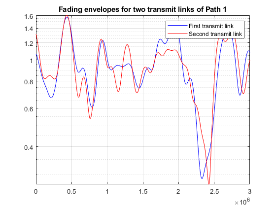
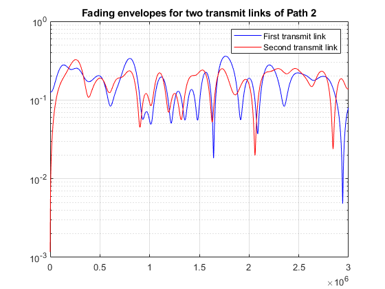
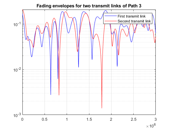
We compute the spatial correlation matrices for each path. We observe that they show a match with the theoretical values Rt. Note that corrcoef function estimate can be improved if Ns is increased.
TxCorrMatrixPath1 = corrcoef(g(:,1,1),g(:,1,2)).'
TxCorrMatrixPath2 = corrcoef(g(:,2,1),g(:,2,2)).'
TxCorrMatrixPath3 = corrcoef(g(:,3,1),g(:,3,2)).'
TxCorrMatrixPath1 =

   1.0000 + 0.0000i   0.7537 + 0.0388i
   0.7537 - 0.0388i   1.0000 + 0.0000i


TxCorrMatrixPath2 =

   1.0000 + 0.0000i   0.7605 + 0.2331i
   0.7605 - 0.2331i   1.0000 + 0.0000i


TxCorrMatrixPath3 =

   1.0000 + 0.0000i   0.7113 + 0.1282i
   0.7113 - 0.1282i   1.0000 + 0.0000i
Selected Bibliography
3GPP TS 05.05 V8.20.0 (2005-11): 3rd Generation Partnership Project; Technical Specification Group GSM/EDGE Radio Access™ Network; Radio transmission and reception (Release 1999).
3GPP TS 45.005 V7.9.0 (2007-2): 3rd Generation Partnership Project; Technical Specification Group GSM/EDGE Radio Access Network; Radio transmission and reception (Release 7).
3GPP TR 25.943 V6.0.0 (2004-12): 3rd Generation Partnership Project; Technical Specification Group Radio Access Network; Deployment aspects (Release 6).
IEEE 802.16 Broadband Wireless Access Working Group, "Channel models for fixed wireless applications", IEEE 802.16a-03/01, 2003-06-27.