Interference Modeling
This example shows interference modeling in a bent pipe satellite communications link using Communications Toolbox™.
Introduction
Signal interference is the addition of unwanted signals to a desired signal and is a common problem in many communications systems. Some examples of interference are:
The coexistence of 5G and LTE waveforms in the same or similar frequency bands results in one waveform interfering with another waveform
Signals from a secondary base station interfering with the signal from the primary base station at a mobile device
Downlink adjacent satellite interference occurs when the ground receiving antenna receives significant signal levels from beams of adjacent satellites
Interference occurs when a satellite receives and re-broadcasts a strong uplink signal from secondary ground station
Modeling such interference scenarios allows you to analyze their impact on system performance and to design mitigation strategies.
System Setup
The InterferenceModelingExample model simulates a bent pipe satellite communication link and illustrates how to model an uplink interference scenario. A bent pipe link consists of an uplink from a ground station to a satellite, which acts as a repeater, and downlinks to another ground station without performing any bit-level processing. The satellite transponder receives a primary signal and an interfering signal from a secondary ground station. The combined signal is re-broadcast by the satellite, received and processed at the ground station.
A Multiband Combiner block provides an efficient approach to combine the primary and the interfering signals at baseband. The Multiband Combiner block interpolates the two signals so that the resulting sample rate of the signals guarantees no aliasing when the signals are frequency shifted to model the interference scenario. Then it applies the specified frequency shifts to the signals and combines them into one signal. The block allows modeling of various amounts of spectral overlap to simulate varying severity of interference. For more information, see the Multiband Combiner block reference page.
System Simulation
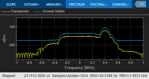
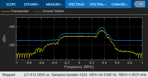
Each of the two baseband signals has a bandwidth of 500 kHz as seen in the Tx Signal Spectrum scope. The Frequency offsets parameter of the Multiband Combiner block is set up to model spectral overlap of 100 kHz. This spectral overlap is seen in the Rx Signal Spectrum that shows the spectra of the signals received at the satellite transponder and ground station receiver.
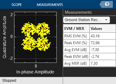
A bit error rate of 0 shows that the system performance is not degraded by this amount of interference. Also, the Received Signal Constellation at the ground station receiver is well clustered around the reference QPSK constellation of the primary signal with a low RMS EVM.


Increase the interference effect by increasing the spectral overlap between the two signals. The increased interference degrades the system performance, as seen from the nonzero bit error rate and a more spread out received signal constellation with higher RMS EVM.


Summary and Further Exploration
This example illustrates a technique to model signal interference that is common in many wireless communications systems. The Multiband Combiner block encompasses the necessary processing of interpolation, frequency shift and signal combining required to simulate various interference scenarios. Other ways to explore interference with this model include:
Use baseband signals with different bandwidths
Activate and deactivate interference by using the switch in the 'Interfering Signal' subsystem
Model more than two baseband signals and more than one interfering signal
Model various amounts of interference by setting parameters of Signal Aggregator block appropriately
Model various approaches to minimize the impact of interference at the satellite transponder and ground station receiver
Experiment with the Multiband Combiner block and possibly alter the processing necessary for the particular interference scenario. When the Output sample rate options parameter is set to 'Auto', the Multiband Combiner block interpolates the input signals such that the frequency content of the original signals is not distorted after they are frequency shifted. You can also interpolate the baseband input signals to the rate you desire before using the Multiband Combiner block and set the Output sample rate options parameter to 'Specify via property', set Output sample rate to the same value as 'Input sample rate' which will turn off the builtin interpolation. This example uses two signals, but the block can process any number of input signals once they are concatenated into a matrix.
Multiband Signal Generation example illustrates a comm.MultibandCombiner System object™ to perform similar processing as the Multiband Combiner block in MATLAB®.
See Adjacent and Co-Channel Interference example to model the effects of adjacent and co-channel interference on a signal.