Visualize Antenna Coverage Map and Communication Links
This example shows how to calculate and visualize signal strength between a transmitter and multiple receivers. The visualizations include an area coverage map and colored communication links. The example also shows selection of a directional antenna in order to achieve a communication link to a specific location.
Define Transmitter Site
% Define transmitter site at MathWorks (3 Apple Hill Dr, Natick, MA)
fq = 6e9; % 6 GHz
tx = txsite("Name","MathWorks", ...
    "Latitude",42.3001, ...
    "Longitude",-71.3504, ...
    "Antenna",design(dipole,fq), ...
    "AntennaHeight",60, ...        % Units: meters
    "TransmitterFrequency",fq, ... % Units: Hz
    "TransmitterPower",15);        % Units: Watts
Define Receiver Sites
% Define receiver sites in several surrounding towns and cities
rxNames = [...
   "Boston, MA","Lexington, MA","Concord, MA","Marlborough, MA", ...
   "Hopkinton, MA","Holliston, MA","Foxborough, MA","Quincy, MA"];

rxLocations = [...
   42.3601 -71.0589; ... % Boston
   42.4430 -71.2290; ... % Lexington
   42.4604 -71.3489; ... % Concord
   42.3459 -71.5523; ... % Marlborough
   42.2287 -71.5226; ... % Hopkinton
   42.2001 -71.4245; ... % Holliston
   42.0654 -71.2478; ... % Foxborough
   42.2529 -71.0023];    % Quincy

% Define receiver sensitivity. Sensitivity is the minimum signal strength in
% power that is necessary for the receiver to accurately detect the signal.
rxSensitivity = -90; % Units: dBm

rxs = rxsite("Name",rxNames, ...
    "Latitude",rxLocations(:,1), ...
    "Longitude",rxLocations(:,2), ...
    "Antenna",design(dipole,tx.TransmitterFrequency), ...
    "ReceiverSensitivity",rxSensitivity); % Units: dBm
Show Sites on a Map
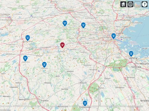
Show the transmitter and receiver sites on a map. You can display information about a site by clicking on a marker.
viewer = siteviewer;
show(tx)
show(rxs)
Set the map imagery by using the Basemap property. Alternatively, open the map imagery picker in Site Viewer by clicking the second button from the right. Select "OpenStreetMap" to see streets and labels on the map. Rotate the view to show an overhead perspective.
viewer.Basemap = "openstreetmap";
Display Idealized Coverage Map using Dipole Antenna
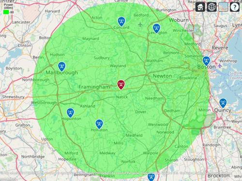
Display coverage map. A coverage map shows the geographic area where a receiver will obtain good reception, which is where transmitted signal strength meets or exceeds the receiver"s sensitivity. Transmitted signal strength in power (dBm) is computed using a free-space propagation model, which disregards terrain, obstacles, and atmospheric effects. As a result, the coverage map shows idealized coverage area in the absence of any path loss impairments beyond free space loss.
coverage(tx,"freespace", ...
    "SignalStrengths",rxSensitivity)

Plot Communication Links using Dipole Antenna
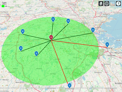
Plot communication links on the map. Red links appear where the receiver is outside of the coverage zone, and green links appear where the receiver is within the coverage zone. Link lines may be clicked to display link statistics. To contrast the colors of the coverage zone and successful links, specify the color of successful links as dark green.
sc = [0 0.3 0];
link(rxs,tx,"freespace","SuccessColor",sc)

Use Rain Propagation Model
Update the coverage map and links to include path loss due to rain. Note that Boston, MA is no longer inside the coverage zone.
coverage(tx,"rain","SignalStrengths", rxSensitivity)
link(rxs,tx,"rain","SuccessColor",sc)

Define Directional Antenna
The dipole antenna transmitter results in a few receiver sites outside of the coverage zone, including the receiver in Boston, MA. Now assume a requirement of the transmitter is to achieve a communication link with Boston. Define a directional antenna that can increase antenna gain in that direction.
% Define Yagi-Uda antenna designed for transmitter frequency
yagiAnt = design(yagiUda,tx.TransmitterFrequency);

% Tilt antenna to direct radiation in XY-plane (i.e. geographic azimuth)
yagiAnt.Tilt = 90;
yagiAnt.TiltAxis = "y";

f = figure;

% Show directivity pattern
patternAzimuth(yagiAnt,tx.TransmitterFrequency)

%Close the previous figure
if (isvalid(f))
    close(f);
end
Display Coverage Map using Yagi-Uda Antenna
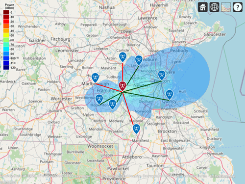
Update the coverage map and links. Boston is now within the coverage zone, but communication links with receivers in other directions are lost.
% Update transmitter antenna
tx.Antenna = yagiAnt;

% Point main beam toward Boston, MA by assigning azimuth angle between
% transmitter location and Boston receiver location
tx.AntennaAngle = angle(tx, rxs(1));

% Update visualizations, using "rain" propagation model
coverage(tx,"rain","SignalStrengths",rxSensitivity)
link(rxs,tx,"rain","SuccessColor",sc)

Display Contoured Coverage Map using Multiple Signal Strengths
When a single signal strength is specified, the coverage map is green for the coverage region. Specify multiple signal strengths to generate a coverage map with contours for different signal levels.
% Define signal strengths from sensitivity to -60 dB
sigStrengths = rxSensitivity:5:-60;

% Update coverage map
coverage(tx,"rain","SignalStrengths",sigStrengths)

See Also
Functions
Objects
txsite|rxsite|siteviewer