Frequency Response Data (FRD) Model with Time Delay
This example shows that absorbing time delays into frequency response data can cause undesirable phase wrapping at high frequencies.
When you collect frequency response data for a system that includes time delays, you can absorb the time delay into the frequency response as a phase shift. Alternatively, if you are able to separate time delays from your measured frequency response, you can represent the delays using the InputDelay, OutputDelay, or ioDelay properties of the frd model object. The latter approach can give better numerical results, as this example illustrates.
The frd model fsys includes a transport delay of 2 s. Load the model into the MATLAB® workspace and inspect the time delay.
load('frddelayexample.mat','fsys')
fsys.IODelay
ans =
2
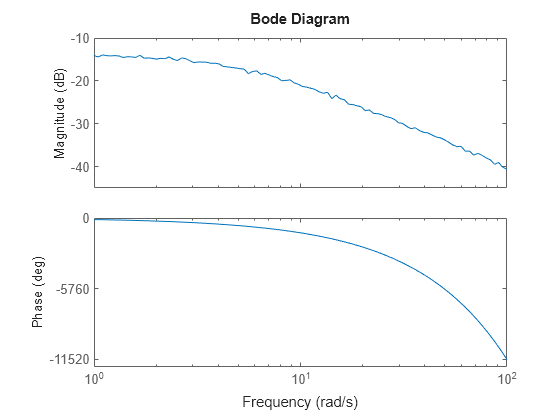
A Bode plot of fsys shows the effect of the transport delay, causing the accumulation of phase as frequency increases.
bodeplot(fsys)

The absorbDelay command absorbs all time delays directly into the frequency response, resulting in an frd model with IODelay = 0.
fsys2 = absorbDelay(fsys);
fsys2.IODelay
ans =
0
Comparing the two ways of representing the delay shows that absorbing the delay into the frequency response causes phase-wrapping.
bode(fsys,fsys2)

Phase wrapping can introduce numerical inaccuracy at high frequencies or where the frequency grid is sparse. For that reason, if your system takes the form , you might get better results by measuring frequency response data for G(s) and using InputDelay, OutputDelay, or ioDelay to model the time delay .