Generate Pulse Width Modulated Signals Using NI Devices
This example shows how to generate a pulse width modulated signal to drive a stepper motor.
Create a Counter Output Channel
Use daq to create a DataAcquisition. Use addoutput to add a counter output channel with PulseGeneration measurement type, and addinput to add an analog input channel to monitor the pulse generated by the counter output channel. For this example, use CompactDAQ chassis NI c9178 and module NI 9402 with ID cDAQ1Mod5 for the pulse generation and NI 9205 with ID cDAQ1Mod1 for the voltage input.
dq = daq("ni");
addinput(dq,"cDAQ1Mod1", "ai0", "Voltage");
ctr = addoutput(dq,"cDAQ1Mod5", "ctr0", "PulseGeneration");
dq.Channels
ans =

    Index    Type      Device       Channel    Measurement Type           Range                 Name
    _____    ____    ___________    _______    _________________    __________________    ________________

      1      "ai"    "cDAQ1Mod1"    "ai0"      "Voltage (Diff)"     "-10 to +10 Volts"    "cDAQ1Mod1_ai0"
      2      "co"    "cDAQ1Mod5"    "ctr0"     "PulseGeneration"    "n/a"                 "cDAQ1Mod5_ctr0"
Determine the Terminal of the Counter Output Channel
To connect the output signal to the correct terminal, examine the Terminal property of the counter channel. The terminal is determined by the hardware.
ctr.Terminal
ans =

    'PFI0'
Clocked Counter Output
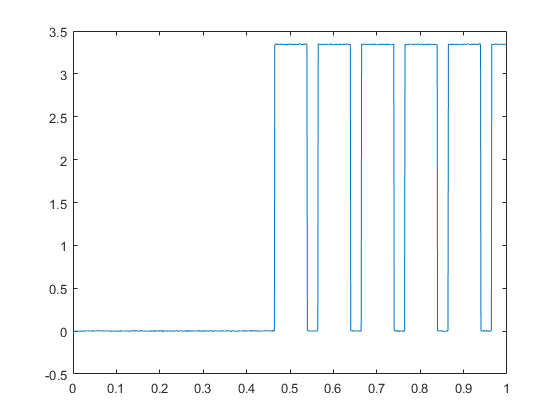
Use counter output channel 0 to generate a fixed pulse width modulated signal on terminal PFI0. Trigger the motor after 0.5 seconds, with a 75% duty cycle.
ctr.Frequency = 10;
ctr.InitialDelay = 0.5;
ctr.DutyCycle = 0.75;

% Starting in foreground returns data for input channels only.
% The data variable will contain one column of data.
start(dq, "Duration", seconds(1));

while dq.Running
    pause(0.1);
end

data = read(dq, seconds(1));
plot(data.Time, data.Variables);
