Measure Strain Using an Analog Bridge Sensor
This example shows how to acquire bridge circuit voltage ratio data using a CompactDAQ module, then compute and plot strain values. This example does not apply to USB devices such as the NI USB-9219.
Discover Devices that Support Bridge Sensor Measurements
To discover a device that supports bridge sensor measurements, access the device in the array returned by daqlist command. For this example use National Instruments® CompactDAQ Chassis NI cDAQ-9178 and module NI 9219 with ID cDAQ1Mod7.
d = daqlist("ni")
d =

  12×4 table

     DeviceID                 Description                    Model             DeviceInfo
    ___________    __________________________________    _____________    ____________________

    "cDAQ1Mod1"    "National Instruments NI 9205"        "NI 9205"        [1×1 daq.DeviceInfo]
    "cDAQ1Mod2"    "National Instruments NI 9263"        "NI 9263"        [1×1 daq.DeviceInfo]
    "cDAQ1Mod3"    "National Instruments NI 9234"        "NI 9234"        [1×1 daq.DeviceInfo]
    "cDAQ1Mod4"    "National Instruments NI 9201"        "NI 9201"        [1×1 daq.DeviceInfo]
    "cDAQ1Mod5"    "National Instruments NI 9402"        "NI 9402"        [1×1 daq.DeviceInfo]
    "cDAQ1Mod6"    "National Instruments NI 9213"        "NI 9213"        [1×1 daq.DeviceInfo]
    "cDAQ1Mod7"    "National Instruments NI 9219"        "NI 9219"        [1×1 daq.DeviceInfo]
    "cDAQ1Mod8"    "National Instruments NI 9265"        "NI 9265"        [1×1 daq.DeviceInfo]
    "Dev1"         "National Instruments PCIe-6363"      "PCIe-6363"      [1×1 daq.DeviceInfo]
    "Dev2"         "National Instruments NI ELVIS II"    "NI ELVIS II"    [1×1 daq.DeviceInfo]
    "Dev3"         "National Instruments PCIe-6363"      "PCIe-6363"      [1×1 daq.DeviceInfo]
    "Dev4"         "National Instruments PCIe-6363"      "PCIe-6363"      [1×1 daq.DeviceInfo]
deviceInfo = d{7, "DeviceInfo"}
deviceInfo =

ni: National Instruments NI 9219 (Device ID: 'cDAQ1Mod7')
   Analog input supports:
      9 ranges supported
      Rates from 0.1 to 100.0 scans/sec
      4 channels ('ai0','ai1','ai2','ai3')
      'Voltage','Current','Thermocouple','RTD','Bridge' measurement types

This module is in slot 7 of the 'cDAQ-9178' chassis with the name 'cDAQ1'.
Create an Analog Input Channel
Create a DataAcquisition and add an analog input channel with the Bridge measurement type. There are two strain gauges connected to the NI 9219 in half bridge configuration.
dq = daq("ni");
dq.Rate = 10;
ch = addinput(dq, "cDAQ1Mod7", "ai0", "Bridge");
Set Channel Properties
You must set the bridge mode according to the bridge circuit configuration and the nominal resistance to the value specified by the strain gauge datasheet. In this example, the strain gauges used are the SGD-3/350-LY13 linear strain gauges from Omega®, with a nominal resistance of 350 ohms, and the bridge is configured as a half-bridge.
ch.BridgeMode = "Half";
ch.NominalBridgeResistance = 350;
Set ADCTimingMode
By default, the ADC timing mode ADCTimingMode of the channel is set to 'HighResolution'. Set the ADCTimingMode to 'HighSpeed'.
ch.ADCTimingMode = "HighSpeed";
Acquire Data
Use read to acquire 10 seconds of data.
data = read(dq, seconds(10));
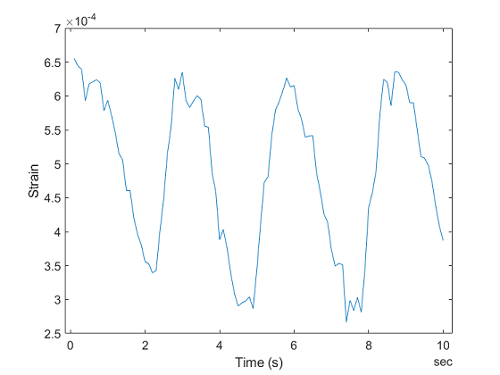
Calculate Strain from Voltage Ratio
The acquired data is the ratio of measured voltage to excitation voltage.
This data is used to compute strain values using a conversion formula (as determined by your bridge configuration).
For half bridge configuration, use
strain = -2*Vr/GF
where GF is gauge factor provided in the sensor data sheet and Vr is the voltage ratio output as measured by your bridge channel.
Assume negligible lead wire resistance in this case. For the strain gauge used in this example, GF = 2.13.
GF = 2.13;
strain = -2*data.cDAQ1Mod7_ai0/GF;
plot(data.Time, strain);
xlabel('Time (s)');
ylabel('Strain');
