Variable Bandwidth IIR Filter
Design tunable bandwidth IIR filter
Libraries:
DSP System Toolbox /
Filtering /
Filter Designs
Description
The Variable Bandwidth IIR Filter block filters each channel of the input signal over time using the IIR filter specifications. This block offers tunable filter design parameters, which enable you to tune the filter characteristics while the simulation is running.
The block designs the IIR filter according to the filter parameters set in the block dialog box. The output port properties, such as datatype, complexity, and dimension, are identical to the input port properties.
Examples
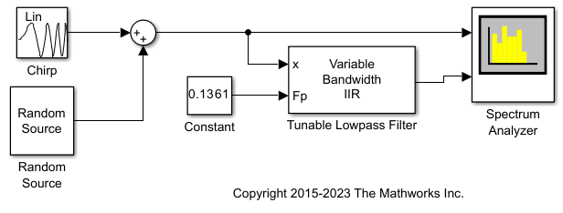
Tunable Lowpass Filtering of Noisy Input in Simulink
Filter a noisy chirp signal with a lowpass filter that has a tunable passband frequency. The filter in this example is designed using a Variable Bandwidth IIR Filter block with Filter type set to Lowpass. This type of filter enables you to change the passband frequency during simulation without having to redesign the whole filter. The filter algorithm recomputes the filter coefficients whenever the passband frequency changes.
Ports
Input
Output
Parameters
Block Characteristics
Data Types |
|
Multidimensional Signals |
|
Variable-Size Signals |
|
Algorithms
This filter covers frequency transformations. The algorithm designs a lowpass IIR prototype
using the elliptical method by specifying its order, passband frequency, passband ripple,
and stopband attenuation. The passband ripple and stopband attenuation are equal to the
values of the PassbandRipple and StopbandAttenuation
properties. The algorithm sets the prototype passband frequency to 0.5. If the
FilterType property is 'Lowpass' or
'Highpass', the order of the prototype filter is equal to the value
of FilterOrder. If the FilterType property is
'Bandpass' or 'Bandstop', the order of the
prototype filter is equal to FilterOrder/2. The prototype is a Direct
Form II Transposed cascade of second-order sections (Biquad filter). The prototype is
transformed into the desired filter using the algorithms used in Digital Frequency Transformations. Each prototype SOS section is transformed
separately. When FilterType is 'Lowpass' or
'Highpass', the resulting filter remains a Direct Form II Transposed
cascade of second order sections. If the FilterType is
'Bandpass' or 'Bandstop', the resulting filter is
a cascade of Direct Form II Transposed cascade of fourth order sections.
References
[1] A. G. Constantinides. "Spectral Transformations for Digital Filters." Proceedings of the Institution of Electrical Engineers 117, no. 8 (1970):1585-1590.