主要内容

FIR Rate Converter (Obsolete)

Upsample, filter, and downsample input signal (with request port)

  • FIR Rate Converter (Obsolete) block

Description

The FIR Rate Converter block upsamples, filters, and downsamples input signals. It is optimized for HDL code generation and operates on one sample of each channel at a time. The block implements a polyphase architecture to avoid unnecessary arithmetic operations and high intermediate sample rates.

High level rate converter architecture

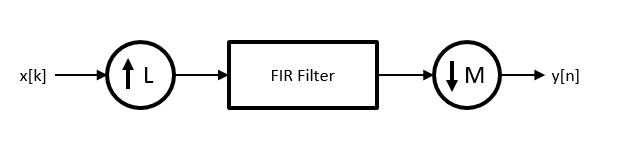
The block upsamples the input signal by an integer factor of L, applies it to a FIR filter, and downsamples the input signal by an integer factor of M.

You can use the input and output control ports for pacing the flow of samples. In the default configuration, the block uses input and output valid control signals. The block has a request port to control the output rate. For input flow control, you can enable a ready output signal.

Architecture diagram that shows the valid, ready, and request control signals

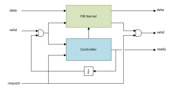
The ready output port indicates that the block can accept a new input data sample on the next time step. When LM, you can use the ready signal to achieve continuous output data samples. If you apply a new input sample after each time the block returns ready signal as 1, the block returns a data output sample with the output valid signal set to 1 on every time step.

When you disable the ready port, you can apply a valid data sample only every ceil(L/M) time steps. For example, if:

  • L/M = 4/5, then you can apply a new input sample on every time step.

  • L/M = 3/2, then you can apply a new input sample on every other time step.

The block returns the next output sample one cycle after the request signal is 1 and a valid output sample is available. When no new data is available, block sets the output valid signal to 0.

You can connect the request input port to the ready output port of a downstream block.

Examples

Ports

Input

expand all

Input data sample, specified as a scalar, or as a row vector in which each element represents an independent channel. The block accepts real or complex data.

The software supports double and single data types for simulation, but not for HDL code generation.

Data Types: single | double | int8 | int16 | int32 | int64 | uint8 | uint16 | uint32 | uint64 | fixed point

Control signal that indicates if the input data is valid. When valid is 1 (true), the block captures the values from the input data port. When valid is 0 (false), the block ignores the values from the input data port.

You can apply a valid data sample every ceiling(L/M) time steps.

Data Types: Boolean

When the request port is 1, and an output data sample is available, on the next cycle the block returns that output data sample on the output data port and sets the output valid signal to 1. When no new data is available, the block sets the output valid signal to 0. When the request port is 0, the block holds available data until the request port is set to 1.

You can connect the request input port to the ready output port of a downstream block.

Data Types: Boolean

Output

expand all

Output data sample, returned as a scalar or a row vector in which each element represents an independent channel.

Data Types: single | double | int8 | int16 | int32 | int64 | uint8 | uint16 | uint32 | uint64 | fixed point

Control signal that indicates if the data from the output data port is valid. When valid is 1 (true), the block returns valid data from the output data port. When valid is 0 (false), the values from the output data port are not valid.

Data Types: Boolean

Control signal that indicates that the block is ready for new input data sample on the next cycle. When ready is 1 (true), you can specify the data and valid inputs for the next time step. When ready is 0 (false), the block ignores any input data in the next time step.

You can connect the ready output port to the request input port of an upstream block.

Dependencies

To enable this port, select the Enable ready output port check box.

Data Types: Boolean

Parameters

expand all

Main

Specify a factor by which the block interpolates the input data sample.

Specify a factor by which the block decimates the input data sample.

Specify a row vector of coefficients in descending powers of z-1.

Note

You can generate filter coefficients using Signal Processing Toolbox™ filter design functions (such as fir1). Design a lowpass filter with normalized cutoff frequency no greater than min(1/L,1/M). The block initializes internal filter states to zero.

Data Types

Select a rounding mode for fixed-point operations. For more information, see Rounding mode.

Specify whether overflows saturate or wrap.

  • off — Overflows wrap to the appropriate value that data type can represent. For example, because 130 does not fit in a signed 8-bit integer, it wraps to -126.

  • on — Overflows saturate to either the minimum or maximum value that data type can represent. For example, an overflow associated with a signed 8-bit integer can saturate to -128 or 127.

FIR filter coefficients data type, specified as a fixdt(s,wl,fl) object with signedness, word length, and fractional length properties.

Specify the data type for the output data samples.

Control Ports

Select this parameter to enable the ready port.

Algorithms

expand all

The FIR Rate Converter block implements a fully parallel polyphase filter architecture. The diagram shows where the block casts the data types based on your configuration.

FIR Rate Converter architecture with data type parameters labeled

Extended Capabilities

expand all

Version History

Introduced in R2015b

expand all