Code Verification and Validation with PIL
This example shows you how to use Embedded Coder® Support Package for Infineon AURIX™ TC4x Microcontrollers for code verification and validation using PIL.
Using this example, you can perform validation of processor-in-the-loop (PIL) in two different modeling scenarios:
Referenced model
Top model
In this example you will learn how to configure a Simulink® model to run PIL. In a PIL simulation, the generated code runs on the Infineon AURIX TC4x hardware boards. The results of the PIL simulation are transferred to Simulink to verify the numerical equivalence of the simulation and the code generation results. The PIL verification process is a crucial part of the development cycle to ensure that the behavior of the deployment code matches the design.
This example introduces the Simulink code generation and verification workflow by showing you how to configure a Simulink model to run PIL simulations on the Infineon AURIX TC4x microcontrollers.
Prerequisites
Complete the Getting Started with Embedded Coder Support Package for Infineon AURIX TC4x Microcontrollers example.
Required Hardware
Infineon AURIX TC4x Hardware Board
Micro-USB cable
Choosing a Communication Interface for PIL Simulation
Choose a communication interface by following the steps below:
1. Open the model. The model is configured for Infineon AURIX TC4x hardware.
2. To run the model on other Infineon AURIX processors, press Ctrl+E to open the Configuration Parameters dialog box and select the required hardware board by navigating to Hardware Implementation > Hardware board.
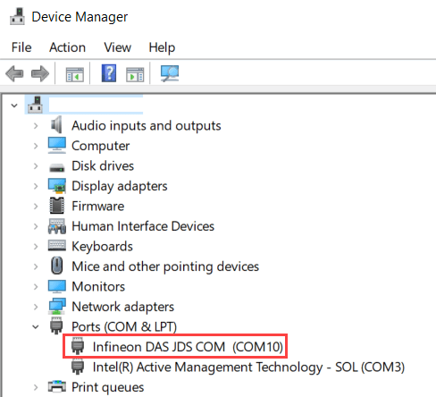
3. Navigate to Configuration Parameters > Hardware Implementation > Target Hardware Resources > Connectivity > Serial port in MATLAB preferences, select the COM port of host computer for PIL simulations.

To find the COM port number of the USB Serial Port showing in your host computer, browse to Device Manager > Ports (COM & LPT) to find the COM port.
Verifying Referenced Model Code Using PIL
This example shows how to verify the generated code for a referenced model by running a PIL simulation. With this approach:
You can verify code generated for referenced models
You must provide a test harness model to provide a test vector or stimulus inputs
You can easily compare the Model block between normal and PIL simulations
1. Open the tc4x_pil_model_block.slx model.
This model contains a referenced model CounterA. Double-click on the referenced model and configure Hardware board by following the steps in the Choosing a Communication Interface for PIL Simulation section.

2. Choose the COM port.
3. Configure and run CounterA Model block in PIL simulation mode.
a. Right click on CounterA block and select Block Parameters (ModelReference)
b. Select Simulation mode > Processor-in-the-loop(PIL) and click OK.

4. Run tc4x_pil_model_block in PIL simulation.
a. Open the Apps tab and select SIL/PIL Manager.
b. On the SIL/PIL tab, set Mode to Automated Verification and click Run Verification.

The SIL/PIL Manager application runs the model in both normal and PIL simulations and launches the Simulation Data Inspector to compare these simulation results.
Verifying Top Model Code Using PIL
This example shows how to verify the generated code for a model by running a PIL simulation. With this approach:
You can verify code generated for a top model
You must configure the model to load test vectors or stimulus inputs from the MATLAB workspace
You can easily switch the entire model between normal and PIL simulation mode
1. Open the tc4x_pil_top_model.slx model.

2. Choose the COM port.
3. Run the top model PIL simulation.
a. Open the Apps tab and select SIL/PIL Manager.
b. On the SIL/PIL tab, set Mode to Automated Verification, SIL/PIL Mode to Processor-in-the-loop(PIL), and click Run Verification.

4. The SIL/PIL Manager application runs the model in both normal and PIL simulations and launches the Simulation Data Inspector to compare these simulation results.
5. When the PIL simulation is completed, a logsOut variable is created in the base workspace. The logsOut data contains PIL simulation results. You can access the logged data for signals count_a and count_b using the following commands:
count_a = get(logsOut,'count_a');
count_a.Values.Data
count_b = get(logsOut,'count_b');
count_b.Values.Data
Note
Infineon AURIX TC4x microcontrollers use STM timer for PIL profiling.