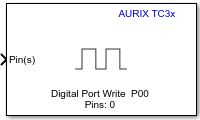
Digital Port Write
Libraries:
Embedded Coder Support Package for Infineon AURIX TC3x
Microcontrollers /
AURIX TC3x
Description
Write logical status of pins of a GPIO port for the Infineon AURIX TC3x Microcontrollers.
Examples
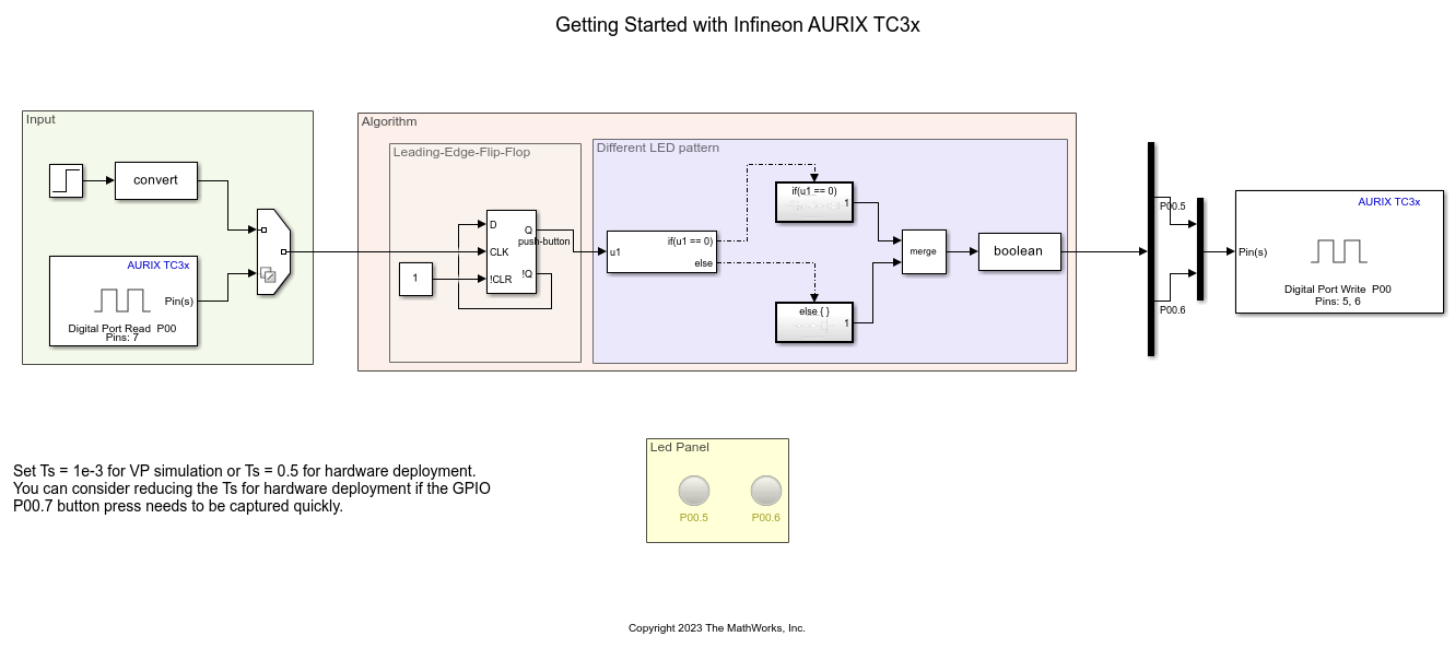
Getting Started with Embedded Coder Support Package for Infineon AURIX TC3x Microcontrollers
Use Embedded Coder® Support Package for Infineon® AURIX™ TC3x Microcontrollers to run a Simulink® model on Infineon AURIX TC3x board.
Signal Monitoring and Parameter Tuning Using Infineon AURIX TC3x Microcontrollers
Use Embedded Coder® Support Package for Infineon® AURIX™ TC3x Microcontrollers in Monitor and Tune mode (External mode) using Infineon AURIX TC3x hardware board.
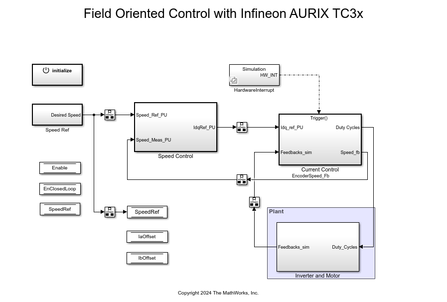
Field-Oriented Control of BLDC with Encoder Using Infineon AURIX TC3xx Microcontrollers
Implement the field-oriented control (FOC) technique to control the speed of a three-phase brushless DC (BLDC) motor. The FOC algorithm requires rotor position feedback, which is obtained by using an encoder sensor. For more details about FOC, see Field-Oriented Control (FOC) (Motor Control Blockset).
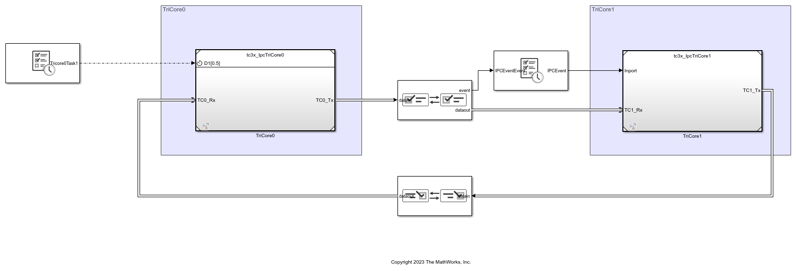
Getting Started with Multicore Modeling and Targeting for Infineon AURIX TC3x Microcontrollers
Use Embedded Coder® Support Package for Infineon® AURIX™ TC3x Microcontrollers to implement multicore modeling and communication between two cores on an Infineon® AURIX™ microcontroller. This example uses a top-level model and two referenced models for two-way multicore data communication. The model supports both simulation and code generation. You can simulate the model and deploy the code on an Infineon AURIX TC3x hardware board using the Soc Builder tool and observe the blinking of the configured LEDs of each core to verify the communication between the cores.
Ports
Input
Specify a value at this port to set the status of GPIO pin(s). You can specify a non-negative scalar or a vector of non-negative elements.
Specify
0
to set the pin(s) to a low value.Specify a
nonzero
value to set the pin(s) to a high value.
The size of input ports available depends on the Number of pins parameter.
Data Types: single
| double
| int8
| int16
| int32
| uint8
| uint16
| uint32
| Boolean
Output
The Digital Port Write block converts the data received at input port into SoC Blockset™ message form and the msg port outputs that message during simulation.
Dependencies
To view this port, select the Enable simulation port parameter and set the port type as SoC Data (Message based).
This port outputs the data received at the input port during simulation.
Dependencies
To view this port, select the Enable simulation port parameter and set the port type as Signal.
Parameters
Select the number of pins (1
to 15
) whose
output you want to configure in the block.
Select this parameter to enable peripheral simulation capability.
Select this parameter to configure either the SoC compatible or the Simulink® signal based simulation ports to enable peripheral simulation capability.
Dependencies
To view this parameter, select the Enable simulation port parameter.
Version History
Introduced in R2024a
MATLAB Command
You clicked a link that corresponds to this MATLAB command:
Run the command by entering it in the MATLAB Command Window. Web browsers do not support MATLAB commands.
Select a Web Site
Choose a web site to get translated content where available and see local events and offers. Based on your location, we recommend that you select: .
You can also select a web site from the following list
How to Get Best Site Performance
Select the China site (in Chinese or English) for best site performance. Other MathWorks country sites are not optimized for visits from your location.
Americas
- América Latina (Español)
- Canada (English)
- United States (English)
Europe
- Belgium (English)
- Denmark (English)
- Deutschland (Deutsch)
- España (Español)
- Finland (English)
- France (Français)
- Ireland (English)
- Italia (Italiano)
- Luxembourg (English)
- Netherlands (English)
- Norway (English)
- Österreich (Deutsch)
- Portugal (English)
- Sweden (English)
- Switzerland
- United Kingdom (English)