SENT Peripheral Configuration
Map data transfer over SENT protocol in the Infineon AURIX model to peripheral registers in the MCU
Since R2024b
Description
Add-On Required: This feature requires the Embedded Coder Support Package for Infineon AURIX TC3x Microcontrollers add-on.
View and edit the map of SENT protocol used in the Infineon® AURIX™ model to the hardware peripherals.
Using the Peripheral Configuration tool, you can:
View and edit configuration parameters for SENT block.
Check for conflicts, if any between peripherals.
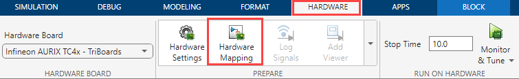
Open the SENT Peripheral Configuration
In the Hardware tab, click Hardware Mapping.
Parameters
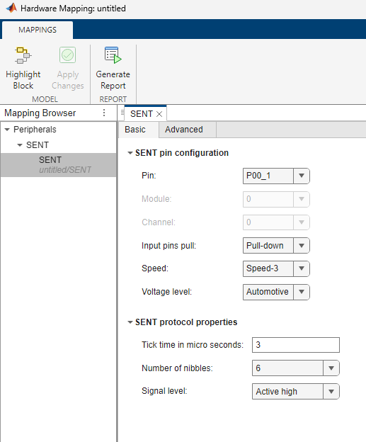
Basic > SENT pin configuration
Select the pin number for reading the data over SENT protocol.
Dependencies
The available pins depend on your selection for the Module parameter.
Select the state of communication line used for SENT protocol.
Select the state of communication line used for SPC mode.
Speed of data transmission over SENT protocol.
Voltage level of the pin based on the application of SENT protocol.
Basic > SENT protocol properties
Tick time to convert the data received over SENT protocol.
Number of nibbles per frame.
Signal level of SENT protocol.
Advanced > Standard frame
CRC check for the standard frame received over SENT protocol.
Option to include Status nibble in CRC check.
Advanced > Slow serial data
Slow serial data processing over SENT channel.
Dependencies
This parameter appears only if you select the Serial parameter in the SENT block in the Simulink® model.
Specify serial frame structure over SENT channel.
Dependencies
This parameter appears if you enable the Serial data processing parameter.
CRC check for serial data received over SENT protocol.
Dependencies
This parameter appears if you enable the Serial data processing parameter.
Advanced > SPC protocol
Select the source of trigger for SPC transmission.
Dependencies
This parameter appears only if you select the SENT
Protocol parameter as SPC.
Select the source of hardware trigger for SPC transmission.
Note
The rising edge of the hardware trigger activates the SPC pulse.
Dependencies
This parameter appears only if you select the Trigger
source parameter as Hardware
trigger.
Select the hardware trigger signal for SPC transmission. The options vary based on the choice of Timer unit and Channel # parameters in PWM Peripheral Configuration tool.
For more information on SENT trigger signals, see SENT Trigger Signals.
Note
The Source of hardware trigger parameter value must match the Timer unit and Channel # parameter values you choose in PWM Peripheral Configuration tool for SENT trigger.
Dependencies
This parameter appears only if you select the Trigger
source parameter as Hardware
trigger.
Specify sensor count for sensor selection.
This parameter decides the number of SPC pulses to configure in the sensor selection mode.
Dependencies
This parameter appears only if you select the SPC Mode
parameter as Sensor selection.
Specify pulse length for SPC pulse #.
Note
You can configure up to 3 SPC pulses if you set the SPC Mode parameter as Feature selection.
You can configure up to 4 SPC pulses (based on Sensor count parameter) if you set the SPC Mode parameter as Sensor selection.
You must specify a value at the DataSel input port within the range of 1 to 4 depending on the SPC Mode parameter. If you provide a DataSel value outside this range, the block will, by default, consider the pulse length values for the out-of-range SPC pulse as the value provided at the Pulse length 1 in ticks parameter.
Dependencies
This parameter appears only if you select the SENT
Protocol parameter as SPC.
Specify pulse delay for SPC pulse #.
Note
You can configure up to 3 SPC pulses if you set the SPC Mode parameter as Feature selection.
You can configure up to 4 SPC pulses (based on Sensor count parameter) if you set the SPC Mode parameter as Sensor selection.
You must specify a value at the DataSel input port within the range of 1 to 4 depending on the SPC Mode parameter. If you provide a DataSel value outside this range, the block will, by default, consider the pulse delay value for the out-of-range SPC pulse as the value provided at the Pulse- 1 delay length in ticks parameter.
Dependencies
This parameter appears only if you select the SENT
Protocol parameter as SPC.
Advanced > Events
Option to add interrupt for standard data reception.
Option to add interrupt for serial data reception.
Option to add interrupt for communication error (for example, CRC check).
Enabling communication error can trigger interrupt in any of the following cases:
Received synchronization / calibration pulse has deviated by permissible limit from nominal value.
Received synchronization / calibration pulse has deviated by permissible limit from predecessor value.
Wrong number of nibbles are received.
Nibble value received is outside range of 0 to 15.
Status and communication nibble is wrong, that is, start bit is 1 in frame other than n-by-16.
CRC check for serial data has failed.
Option to add interrupt for receive buffer overflow error.
Option to add interrupt for transmit buffer underflow error.
Option to add interrupt for watchdog error.
Service request line for the interrupts (based on the above parameters, if selected).
Note
All interrupts for a selected SENT module are serviced using a single service request line.
Dependencies
Service request line is enabled only if at least one of the above mentioned interrupt events are enabled.
Advanced > Miscellaneous
Option to add digital filter depth.
Option to enable frequency drift for data transmission over SENT protocol.
Option to ignore pause pulse for data transmission over SENT protocol.
Advanced > Nibble order
Eight groups of receive data bits - Receive data bits[0:3] to Receive data bits[28:31]. Select the nibble number for each of the eight groups to form the 32-bit data output.
Version History
Introduced in R2024b
See Also
MATLAB Command
You clicked a link that corresponds to this MATLAB command:
Run the command by entering it in the MATLAB Command Window. Web browsers do not support MATLAB commands.
选择网站
选择网站以获取翻译的可用内容,以及查看当地活动和优惠。根据您的位置,我们建议您选择:。
您也可以从以下列表中选择网站:
如何获得最佳网站性能
选择中国网站(中文或英文)以获得最佳网站性能。其他 MathWorks 国家/地区网站并未针对您所在位置的访问进行优化。
美洲
- América Latina (Español)
- Canada (English)
- United States (English)
欧洲
- Belgium (English)
- Denmark (English)
- Deutschland (Deutsch)
- España (Español)
- Finland (English)
- France (Français)
- Ireland (English)
- Italia (Italiano)
- Luxembourg (English)
- Netherlands (English)
- Norway (English)
- Österreich (Deutsch)
- Portugal (English)
- Sweden (English)
- Switzerland
- United Kingdom (English)