Read ADC Values Using Timer-Triggered Interrupts on Renesas RA Microcontrollers
R2026bThis example shows how to use the ADC (Analog-to-Digital Converter) blocks in the Embedded Coder® Support Package for Renesas® RA Microcontrollers to read analog input values using timer-triggered interrupts.
The example demonstrates how to:
Configure the ADC to trigger on timer events.
Use scan-end interrupts to read ADC samples in a function-call subsystem.
Configure double-trigger mode to capture two ADC samples per timer cycle.
Read the internal temperature sensor and compute temperature using calibration data.
Prerequisites
Before you begin,
Complete these tutorials:
Review the MCK-RA6T2 User's Manual.
Complete the Hardware Setup for Embedded Coder Support Package for Renesas RA Microcontrollers.
Required Hardware
Supported Renesas RA hardware board (EK-RA6M2)
USB cable
Jumper wires
Hardware Connection
Connect the jumper wires as follows:
Connect P305 and P005 pins
When using an FTDI adapter for communication between the host computer and the Renesas RA6T2 target board, make the following connections.
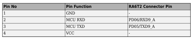
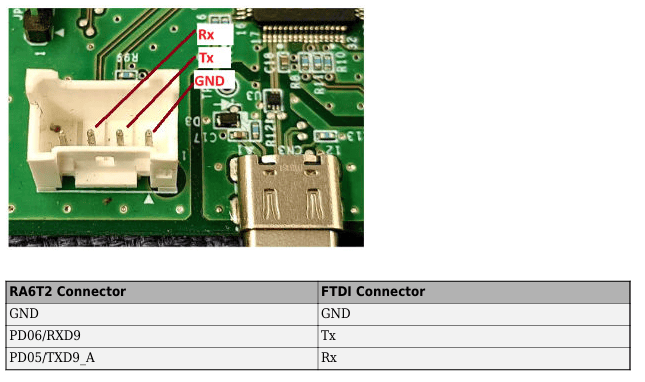
The Rx, Tx, and GND labels shown in red in the figure indicate the corresponding pins on the FTDI connector.
RASC Project File
This example uses a Renesas Smart Configurator (RASC) project file to define the hardware and peripheral configuration required for ADC conversion and timer-triggered interrupts.
The RASC project file configures the following components:
Target hardware: RA6M2 microcontroller on the EK-RA6M2 board (Cortex®-M4 core)
Flexible Software Package (FSP): Version 6.3.0 for peripheral drivers and board support
ADC configuration (r_adc)
Configured for timer-triggered conversion
Unit 1 Scan End interrupt enabled
Supports single and double trigger modes
GPT timer configuration (g_timer0)
Configured to trigger ADC at every 500ms
Supports up and down count trigger for double-trigger mode
Pin configuration
P305 configured as ADC analog input
P106 configured as GPIO output to drive the LED
Peripheral drivers
ADC (Analog-to-Digital Converter)
GPT (General PWM Timer)
IOPORT (pin configuration)
UART (for external mode communication)
Model Overview
This example uses three Simulink® models:
AdcgettingStarted.slx— Demonstrates reading the internal temperature sensor using ADC and computing temperature from calibration data.AdcInterrupt.slx— Demonstrates timer-triggered ADC with single trigger and scan-end interrupt.AdcInterruptDoubleTrigger.slx— Demonstrates timer-triggered ADC configured for double trigger to capture two samples per cycle.
Run the ADC Getting Started (Temperature Sensor) Model
This model demonstrates how to:
Read the internal temperature sensor using the ADC block
Compute temperature using factory calibration data
1. Open the adcInterrupt.slx Simulink model.
modelName = "adcGettingStarted";
open_system(modelName) 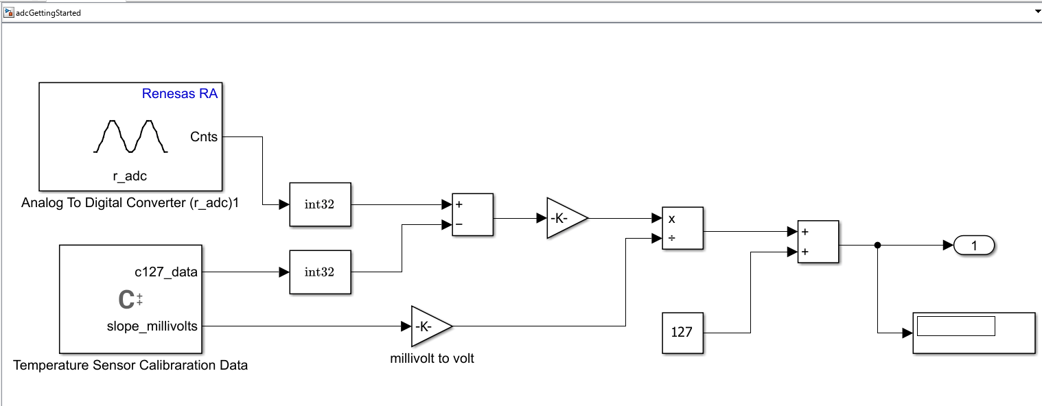
The model uses the following components:
Analog To Digital Converter (r_adc) block: Reads the internal temperature sensor ADC counts.
Temperature Sensor Calibration Data: A C Function block providing calibration values (
c127_dataandslope_millivolts).Temperature computation: The model computes the temperature using the formula:
Temperature = ((ADC_counts - c127_data) * slope_millivolts / 1000) + 127c127_datais the ADC value at 127°C andslope_millivoltsis the temperature slope from calibration data.
Display: A Display block shows the computed temperature over time.
2. Ensure the following settings are applied:
configuration.xmlis added as the Renesas Smart Configurator (RASC) project file in Build options. To verify click Modeling > Model Settings to open the Configuration Parameters dialog box. Navigate to Hardware Implementation > Target hardware resources > Build options.
3. Run the model in External mode.
In the Simulink model, click Hardware tab and then click Monitor & Tune.

4. Observe the model behavior.
The ADC continuously reads the internal temperature sensor.
The computed temperature value is displayed on the scope.
The temperature value should be close to the ambient temperature of the board.
Run the ADC Interrupt (Single Trigger) Model
This model demonstrates how to:
Trigger ADC conversion using a timer event
Read ADC output in a function-call subsystem triggered by the scan-end interrupt
Toggle an LED to indicate active sampling
1. Open the adcInterrupt.slx Simulink model.
modelName = "adcInterrupt";
open_system(modelName) 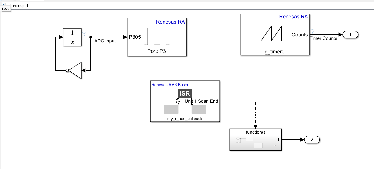
The model contains the following key components:
ADC Input: A unit delay block generates the analog input signal connected to GPIO Port P3 (pin P305).
Timer (g_timer0): Generates timer counts and triggers the ADC at every 500ms.
ISR (Unit 1 Scan End): The
my_r_adc_callbackinterrupt service routine triggers the Function-Call Subsystem when the ADC scan completes.Function-Call Subsystem: Reads the ADC value and toggles an LED.
2. Open the Function-Call Subsystem to view its contents.
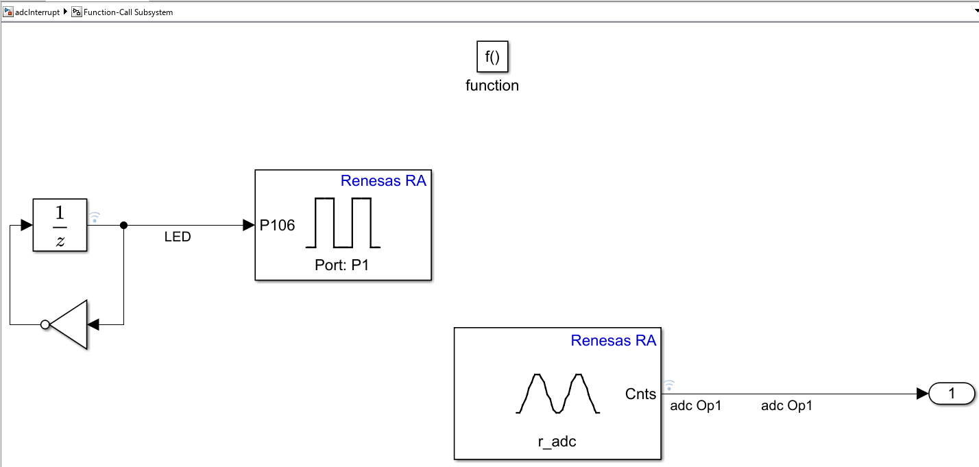
The Function-Call Subsystem contains:
LED toggle: A unit delay with NOT gate drives pin P106 (Port P1) to toggle the onboard LED.
ADC read (r_adc) block: Reads the current ADC count value and outputs it as
adc Op1.
3. Ensure the following settings are applied:
configuration.xmlis added as the Renesas Smart Configurator (RASC) project file in Build options. To verify click Modeling > Model Settings to open the Configuration Parameters dialog box. Navigate to Hardware Implementation > Target hardware resources > Build options.
The model is pre-configured for Renesas RA6 Based hardware.
The example model has these default configurations:
ADC is configured to trigger with timer trigger
Timer is triggering ADC at every 500ms
ADC input is updated every 2 seconds
4. Run the model in External mode.
In the Simulink model, click Hardware tab and then click Monitor & Tune.

5. Observe the model behavior.
The LED toggles each time the scan-end interrupt fires.
The ADC output value reflects the analog voltage on pin P305.
A new ADC sample is captured every 500ms.
Run the ADC Interrupt (Double Trigger) Model
This model demonstrates how to:
Configure the ADC for double trigger mode
Capture two ADC output samples for each timer cycle
Trigger at both up and down counting of the carrier wave (counter)
1. Open the adcInterruptDoubleTrigger.slx Simulink model.
modelName = "adcInterruptDoubleTrigger";
open_system(modelName) 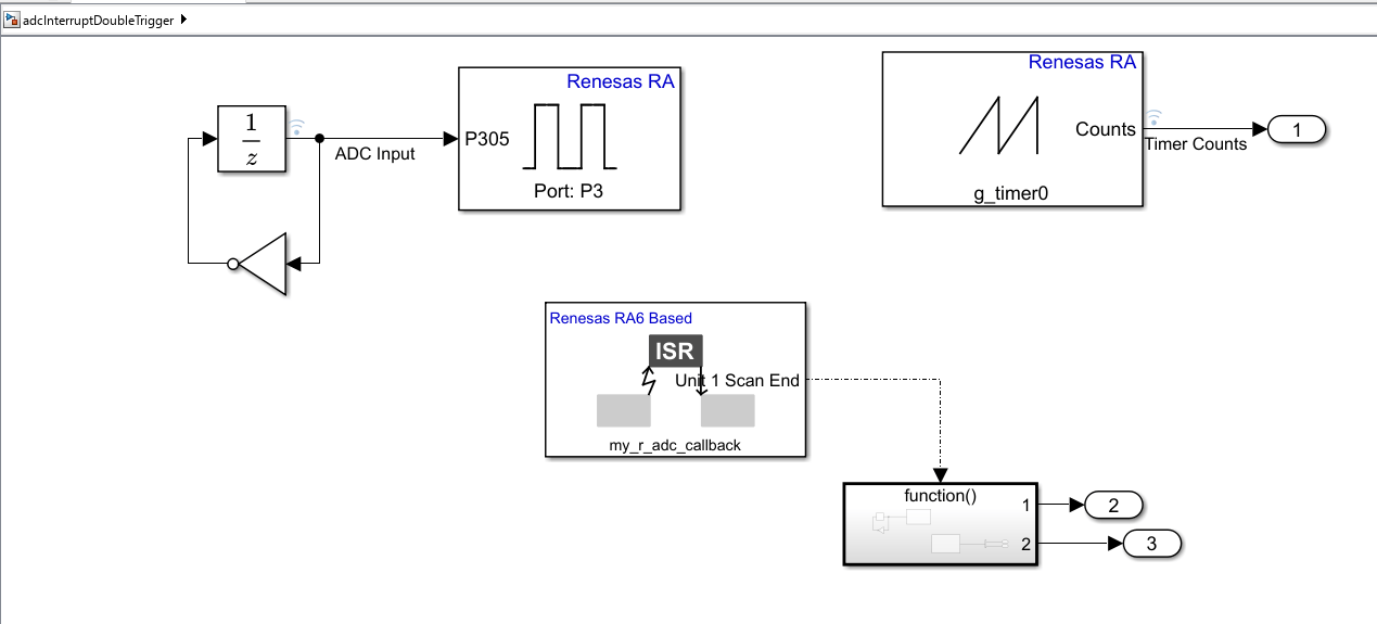
The model is similar to the single trigger model with the following key differences:
The timer trigger is configured so that it will trigger at up and down counting of carrier wave (counter), at a certain timer count.
There are two output samples for each cycle of the counter.
The scan end complete interrupt is triggered only once per cycle.
Around t=2, the ADC output samples have two different values as the value has changed between the up and down count of the timer.
2. Open the Function-Call Subsystem to view its contents.
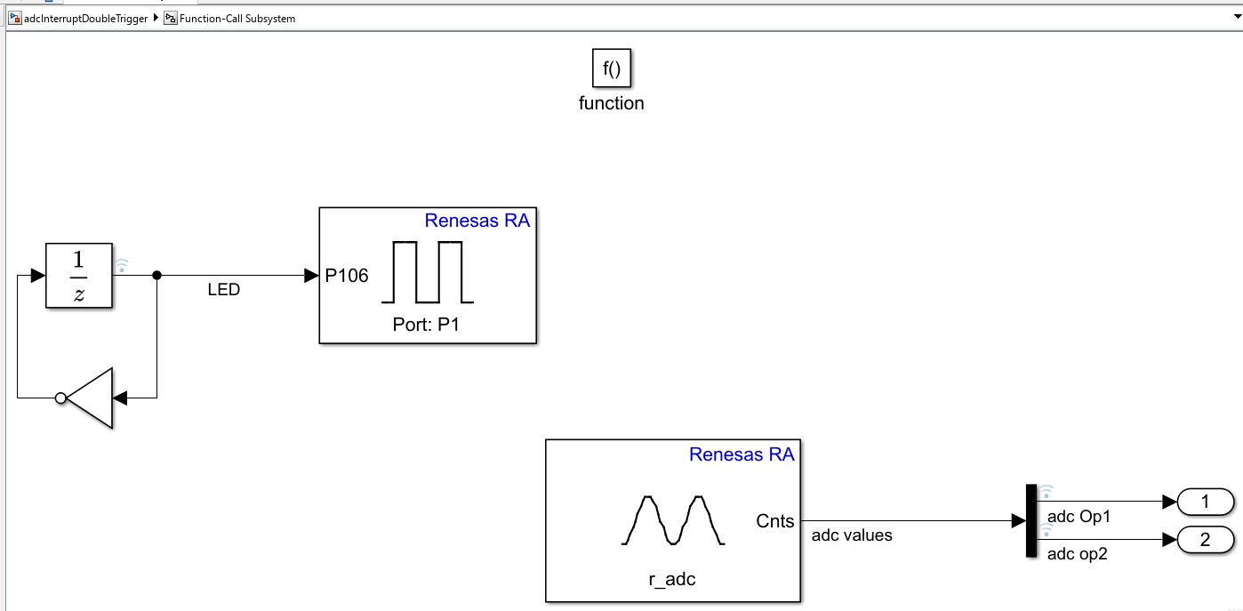
The Function-Call Subsystem for double trigger mode contains:
LED toggle: A unit delay with NOT gate drives pin P106 (Port P1) to toggle the onboard LED.
ADC read (r_adc): Reads the ADC count values and outputs two samples:
adc Op1andadc op2, corresponding to the up-count and down-count trigger events.
3. Ensure the following settings are applied:
configuration.xmlis added as the Renesas Smart Configurator (RASC) project file in Build options. To verify click Modeling > Model Settings to open the Configuration Parameters dialog box. Navigate to Hardware Implementation > Target hardware resources > Build options.
4. Run the model in External mode.
In the Simulink model, click Hardware tab and then click Monitor & Tune.
5. Observe the model behavior.
Two ADC output samples are captured every 500ms (one on up-count, one on down-count).
The ADC input is updated every 2 seconds.
Around t=2 seconds, the two ADC samples have different values because the input value changed between the up and down count triggers.
The scan-end interrupt fires once per timer cycle regardless of the number of triggers.
Other Things to Try
Change the timer period to modify the ADC sampling rate and observe the effect on output resolution.
Modify the double trigger model to use different trigger count values.
Add additional ADC channels to sample multiple analog inputs simultaneously.
Use the temperature sensor model to implement a temperature monitoring application with threshold alerts.

