Control PWM Output Using POEG Triggers on Renesas RA Microcontrollers
R2026bThis example shows how to use the POEG (Port Output Enable for GPT) feature in the Embedded Coder® Support Package for Renesas® RA Microcontrollers to control PWM output using both software and hardware triggers.
The example demonstrates how POEG disables and re-enables PWM output based on:
Software control signals.
External hardware trigger input.
A PWM signal generated by the GPT peripheral drives an onboard LED. When the PWM output is enabled, the LED varies in intensity based on the duty cycle. When a POEG trigger occurs, the PWM output is disabled and the LED turns off. Re-enabling the PWM output restores the LED output.
Prerequisites
Before you begin,
Complete these tutorials:
Review the MCK-RA6T2 User's Manual.
Complete the Hardware Setup for Embedded Coder Support Package for Renesas RA Microcontrollers.
Hardware Connection
Use a jumper wire to route the configured PWM output pin to the GPIO pin that drives the onboard LED, if required by your board configuration.
When using an FTDI adapter for communication between the host computer and the Renesas RA6T2 target board, make the following connections.
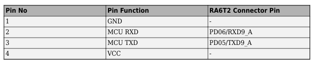

The Rx, Tx, and GND labels shown in red in the figure indicate the corresponding pins on the FTDI connector.
RASC Project File
This example uses a Renesas Smart Configurator (RASC) project file to define the hardware and peripheral configuration required for PWM generation and POEG control.
The RASC project file configures the following components:
Target hardware: RA6T2 microcontroller on the RA6T2-MCK board (Cortex®-M33 core)
Flexible Software Package (FSP): Version 6.3.0 for peripheral drivers and board support
GPT timer configuration
Configured in symmetric PWM mode
Generates the PWM signal used to drive the LED
Linked to a POEG channel for output disable control
Configured with output disable settings to safely control GTIOC pins during POEG events
POEG configuration
Configured to monitor a hardware trigger input pin
Disables GPT PWM output when a trigger event occurs
Supports software re-enabling of PWM output
Pin configuration
Use a jumper wire to route the PWM output pin PB04 to LED2 (PD02) on the 1st Inverter Board Connector (CN5).
When using Hardware Trigger model, connect POEG trigger input PA12 (GTETRGB) to GPIO output PB15.
GPIO and peripheral pin modes configured through the pin configuration file
Clock configuration
PLL-based system clock setup
GPT peripheral clock sourced from PLL
Peripheral drivers
GPT (General PWM Timer)
POEG (Port Output Enable for GPT)
IOPORT (pin configuration)
UART (for external mode communication)
The RASC project file ensures that the GPT and POEG modules are correctly configured and linked. These settings ensure that the PWM and POEG modules work together to control PWM output during trigger events.
Models
This example uses two Simulink® models:
POEGSoftwareTrigger.slx— Demonstrates software-triggered POEG controlPOEGHardwareTrigger.slx— Demonstrates hardware-triggered POEG control.
Run the Software Trigger Example
This model demonstrates how to:
Disable PWM output using a software stop signal.
Re-enable PWM output using a software start signal.
1. Open the POEGSoftwareTrigger.slx Simulink model.
modelName = "POEGSoftwareTrigger";
open_system(modelName) 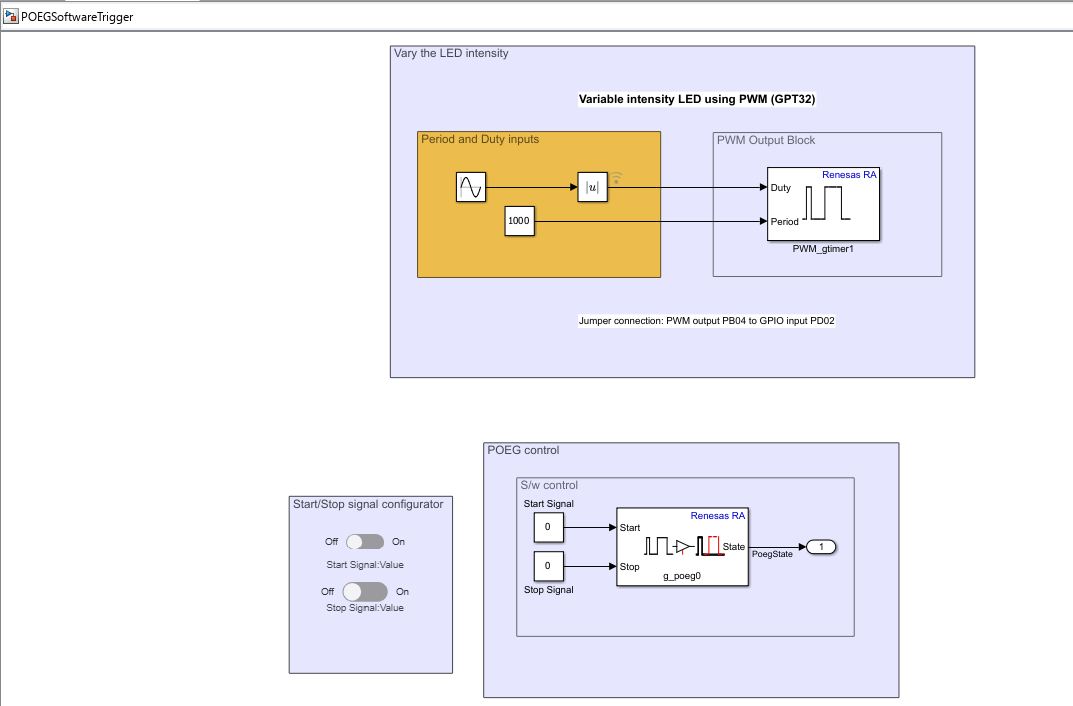
The model is pre-configured for Renesas RA6 Based hardware.
2. Ensure the following settings are applied:
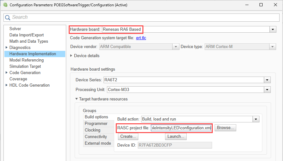
configuration.xmlis added as the Renesas Smart Configurator (RASC) project file in Build options. To verify click Modeling > Model Settings to open the Configuration Parameters dialog box. Navigate to Hardware Implementation > Target hardware resources > Build options.
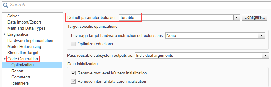
Click Code Generation > Optimization and ensure Default parameter behavior parameter is set to
Tunable.
The example model has these default signal values:
Start PWM signal =
0Stop PWM signal =
0
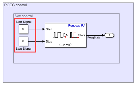
Enable parameter tuning in External mode.
In the Simulink model, click the Hardware tab and select Monitor & Tune. This allows you to update signal values during executio
3. Run the model in External mode.
In the Simulink model, click Hardware tab and then click Monitor & Tune.

Observe that:
The LED glows with varying intensity (PWM output active).
4. Set the Stop Signal to 1.
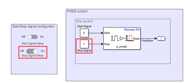
The POEG disables the PWM output.
The LED turns off.
3. Set the Stop Signal back to 0.
4. Set the Start Signal to 1.
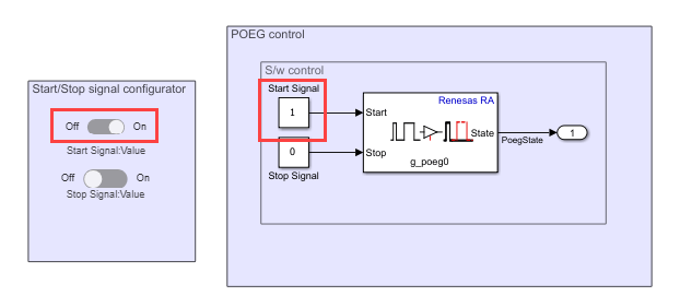
The POEG clears the disable condition.
The PWM output resumes.
The LED glows again.
Run the Hardware Trigger Simulink Model
1. Open the POEGHardwareTrigger.slx Simulink model.
modelName = "POEGHardwareTrigger";
open_system(modelName) 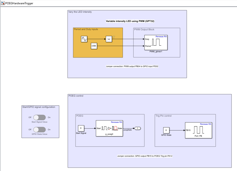
The model is pre-configured for Renesas RA6 Based hardware.
2. Ensure the following settings are applied:
configuration.xmlis added as the Renesas Smart Configurator (RASC) project file in Build options. To verify click Modeling > Model Settings to open the Configuration Parameters dialog box. Navigate to Hardware Implementation > Target hardware resources > Build options.Click Code Generation > Optimization and ensure Default parameter behavior parameter is set to
Tunable.
3. Ensure the default signal values:
Start Signal =
0GPIO State =
0
4. Run the model in External mode.
In the Simulink model, click Hardware tab and then click Monitor & Tune.

Observe that the LED glows with varying intensity, indicating that PWM output is active.
4. Set the GPIO State to 1.The hardware trigger activates POEG, disables the PWM output, and turns off the LED.
5. Set the GPIO Signal back to 0.
6. Set the Start Signal to 1.The POEG block clears the disable condition, and the PWM output resumes. The LED glows again.
Other Things to Try
Change the duty cycle input to observe how LED brightness varies when PWM output is enabled.
Configure the POEG trigger polarity in the model or RASC file and observe how it affects the disable behavior.

