MCAL ADC
Libraries:
Embedded Coder Support Package for Renesas RH850 Microcontrollers /
Microcontroller Abstraction Layer (MCAL) Blocks
Description
Use the MCAL ADC block to trigger ADC group or read analog to digital conversion results of an ADC group or both. An ADC group represents a collection of physical analog input channels configured together.
The block initializes the specified ADC group to sample the associated analog pins and outputs the converted digital values. When reading conversion results, the block output is a 1-by-N row vector, where N is the number of channels configured in the ADC group.
For information on configuring and using ADC with MCAL, see Getting Started with ADC Using MCAL. This tutorial walks through configuring ADC groups in the MCAL configuration tool, selecting the Configuration Description File (CDF) in the model, and using the MCAL ADC block to trigger conversions and read results on Renesas RH850 targets.
Examples
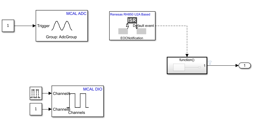
Using MCAL ADC and Hardware Interrupt Blocks with Renesas RH850 Microcontrollers
Acquire analog signals using the MCAL ADC block in a Simulink® model and process the results using the Hardware Interrupt block on a Renesas RH850/U2A16 starter kit. You can use this approach to generate software-triggered ADC conversions, handle end-of-conversion interrupts, and read multiple ADC channels in real time.
Ports
Input
Convert analog signal on ADC input pin to digital signal.
Triggers the ADC input pin for conversion.
1- ADC start of conversion is triggered.0- ADC start of conversion is not triggered.
Dependencies
To enable this port, set the Trigger mode parameter
to Trigger only or Trigger and
read.
Data Types: Boolean
Stops the analog to digital conversion on the ADC input pin.
on- Adds a stop conversion input port to the block.off- The block does not include a stop conversion input port.
Dependencies
To enable this port, set the Trigger mode parameter
to Read results only and then select Enable
stop conversion input parameter.
Data Types: Boolean
Output
The block outputs conversion result of the configured ADC group as a 1-by-N vector where N is the number of channels configured in the block.
Dependencies
To enable this port, set the Trigger mode parameter
to either Trigger and read or Read results
only.
Data Types: uint16
The block outputs the ADC Trigger mode action status.
When the trigger mode is Trigger and Read or Read results only the block outputs the following status:
0- output data is valid conversion results.1- conversion results are not available.
When the trigger mode is Trigger only the block outputs the following status:
0- when ADC is triggered1- when ADC is not triggered
Dependencies
To enable this port, select the Output status parameter.
Data Types: uint16
Parameters
Specify the ADC group short name as configured in the third-party configuration tool. If the target is selected on the Model configuration parameter and the configuration definition file is added, then click Get group details to details of all the ADC groups configured in the CDF.
Programmatic Use
Block Parameter:
GroupId
|
Select one of these option to trigger the conversion.
Trigger and read— Select this option to trigger ADC start of conversion at every sample time. The block output waits until the conversion is complete and emits the results. This option enables the output port Cnts.Trigger only— This option starts the ADC group conversion. Use this option to read the ADC conversion results in triggered or enabled subsystems. As the block does not show the conversion results in this mode, use another Analog to Digital Converter block with the Trigger mode parameter set to Read results only to display the conversion results.Read results only— Select this option to read the newly converted ADC data. If no new data is available, the block outputs the status as1. This option also enables the output port Cnts.
Note
In Trigger and read option, the block actively waits for the ADC conversion to complete by repeatedly querying the MCAL driver status before producing output data. If an ADC group is configured for continuous conversion, do not use Trigger and read to read conversion results. Instead, use Trigger only to start the conversion and Read results only to retrieve the results.
Do not use Trigger and read together with Read results only for the same ADC group.
Programmatic Use
Block Parameter:
TriggerMode
|
Specify the number whose conversion results are to be read in the block. This value should be less than or equal to the number of channels configured for the ADC group in the CDF.
Programmatic Use
Block Parameter:
NumberOfConversions
|
Select the data type for the ADC conversion results. This value is determined
by the resolution of the ADC hardware. This value must match the data type defined
by the target MCAL package. For Renesas RH850 U2A based targets, the required data
type is uint16.
Dependencies
To enable the Output data type parameter, set the
Trigger mode parameter to either Trigger
and read or Read results
only.
Programmatic Use
Block Parameter:
OutputDataType
|
Select this option to enable an input port that can be used to stop the ongoing ADC conversion. When enabled, an additional input port StopConv appears on the block, allowing external logic to halt the current conversion process.
on- adds a stop conversion input port to the block.off- The block does not include a stop conversion input port.
Dependencies
To enable the Enable stop conversion input parameter,
set the Trigger mode parameter to Read
results only.
Programmatic Use
Block Parameter:
StopConversionInput
|
When you select this parameter, the block configures Status output port. The Status port outputs the status of the ADC conversion.
Dependencies
To enable the Output status parameter, set the
Trigger mode parameter to either Trigger
and read or Read results
only.
Programmatic Use
Block Parameter:
OutputStatus
|
Specify how often (in seconds) the block reads the pin value. Enter a value greater than zero. When you specify this parameter as -1, Simulink® determines the best sample time for the block based on the block context within the model.
Applicability by Trigger Mode:
Trigger and read — Sample time controls how often the block triggers a conversion and waits for results.
Trigger only — Sample time controls how often the ADC start-of-conversion is issued.
Read results only — Sample time controls how often the block checks for newly available conversion results.
Dependencies
To enable the Sample time parameter, set the
Trigger mode parameter to either Trigger
and read or Read results
only.
Programmatic Use
Block Parameter:
SampleTime
|
Version History
Introduced in R2026a
MATLAB Command
You clicked a link that corresponds to this MATLAB command:
Run the command by entering it in the MATLAB Command Window. Web browsers do not support MATLAB commands.
选择网站
选择网站以获取翻译的可用内容,以及查看当地活动和优惠。根据您的位置,我们建议您选择:。
您也可以从以下列表中选择网站:
如何获得最佳网站性能
选择中国网站(中文或英文)以获得最佳网站性能。其他 MathWorks 国家/地区网站并未针对您所在位置的访问进行优化。
美洲
- América Latina (Español)
- Canada (English)
- United States (English)
欧洲
- Belgium (English)
- Denmark (English)
- Deutschland (Deutsch)
- España (Español)
- Finland (English)
- France (Français)
- Ireland (English)
- Italia (Italiano)
- Luxembourg (English)
- Netherlands (English)
- Norway (English)
- Österreich (Deutsch)
- Portugal (English)
- Sweden (English)
- Switzerland
- United Kingdom (English)

