Getting Started With DIO Using MCAL
This topic explains how to design a correct and portable Digital Input/Output (DIO) workflow using the MCAL DIO module in Simulink and AUTOSAR-based projects. It helps you choose the right DIO access pattern and pin configuration strategy before you integrate digital I/O into a target-specific model.
This topic describes multiple DIO workflows that differ in how pins are accessed and grouped. You can use these workflows to align digital I/O behavior with your control logic, performance needs, and code generation constraints.
This topic assumes that DIO channels, ports, and channel groups are defined in the AUTOSAR MCAL configuration using Vector DaVinci Configurator. The Port and DIO module configuration determines which pins are eligible for digital I/O access and how they are grouped.
See Configuring MCAL Modules Using DaVinci for instructions on defining Port and DIO configuration and exporting the configuration for code generation.
What Is MCAL?
The Microcontroller Abstraction Layer (MCAL) is the lowest layer of the AUTOSAR Basic Software stack. It provides standardized APIs for accessing on-chip peripherals and memory-mapped external devices, enabling portability of application software across different microcontrollers.
What Is the DIO MCAL Module?
The DIO MCAL module provides runtime access to digital pins through standardized AUTOSAR APIs. It supports:
Read the logical level of digital input pins.
Set or change the logical level of digital output pins.
Access multiple pins as a port or as a logical channel group.
The DIO module abstracts hardware-specific register access and exposes standardized AUTOSAR APIs for digital I/O operations.
Relationship Between Port and DIO Modules
In AUTOSAR, pin configuration and pin usage are intentionally separated:
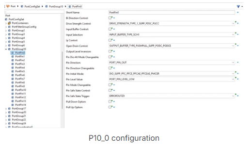
The Port module configures pin characteristics during initialization.
The DIO module provides runtime read and write access to digital pins.
This separation supports functional safety, predictable startup behavior, and controlled runtime access.
DIO Naming Concepts
AUTOSAR defines a structured naming model for digital I/O:
DIO Channel: A single digital pin
DIO Port: A group of channels belonging to the same hardware port
DIO Channel Group: A logical subset of adjacent channels within a port
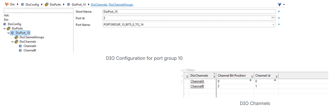
These abstractions allow applications to access digital signals at different granularities without exposing hardware details.
DIO Pin Modes
A digital pin can operate in different modes depending on its configuration:
Port mode: Used as a general-purpose digital input or output
Software-controlled alternate mode: Pin function controlled by software registers
Peripheral-controlled alternate mode: Pin controlled directly by another peripheral
Only pins configured for DIO operation in the Port module are eligible for access through DIO APIs.
Supported DIO Access Patterns
The DIO MCAL module supports multiple access patterns:
Read or write a single channel (pin)
Read or write all channels of a port
Read or write a selected group of channels using a mask
The choice of access pattern affects data types, code generation, and runtime behavior.
Configuration and Code Generation Overview
DIO configuration is authored in an AUTOSAR configuration tool such as Vector DaVinci and exported as AUTOSAR XML. The MCAL code generation process consumes this configuration to produce C source and header files that implement the DIO services for the selected target.
Configuration consistency is validated during code generation. Invalid pin assignments, mismatched channel groups, or unsupported access patterns are detected early, which shifts error detection from runtime to build time.
See Also
Configuring MCAL Modules Using DaVinci | Getting Started with MCAL DIO Blocks on Renesas RH850 Microcontrollers