Model Configuration Parameters for STMicroelectronics STM32F4-Discovery Board
Hardware Implementation Pane Overview
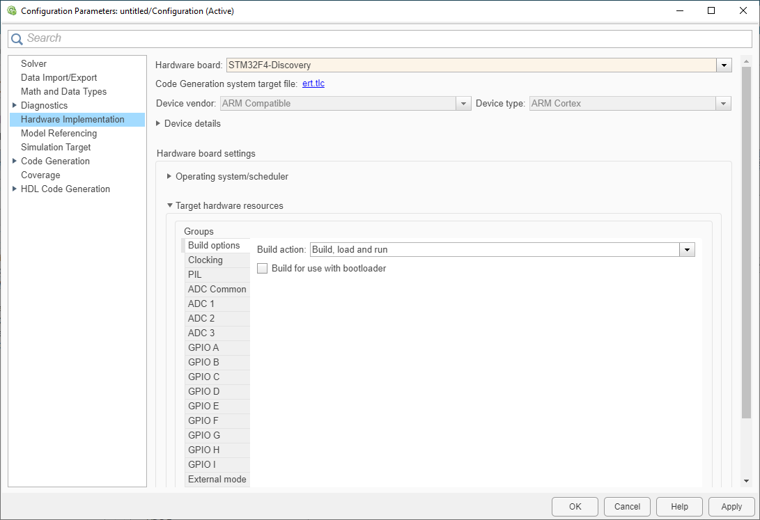
Default Hardware Implementation Pane

Configure hardware board to run Simulink® models.
In the Simulink Editor, select Simulation > Model Configuration Parameters.
In the Configuration Parameter dialog box, click Hardware Implementation.
Set the Hardware board parameter to
STM32F4-Discovery.The parameter values under Hardware board settings are automatically populated to their default values.
You can optionally adjust these parameters for your particular use case.
Click Apply to apply the changes.
For more information on selecting a hardware support package and general configuration settings, see Hardware Implementation Pane.
Operating system options
| Parameter | Description | Default Value |
|---|---|---|
Sets the operating system options to run your model on the selected target hardware. |
|
Scheduler options
| Parameter | Description | Default Value |
|---|---|---|
Sets the static priority of the base rate task in the operating system. |
|
Build options
| Parameter | Description | Default Value |
|---|---|---|
Defines how Embedded Coder® responds when you build your model. |
| |
Defines how to generate a build to use with bootloader. |
| |
Sets the communication interface used by the bootloader. |
| |
Sets the serial port used by the bootloader. |
|
Clocking
| Parameter | Description | Default Value |
|---|---|---|
The CPU clock frequency in MHz. |
|
PIL
| Parameter | Description | Default Value |
|---|---|---|
Sets the interface used for PIL communication. |
| |
Sets the serial port for PIL communication. |
|
ADC Common
| Parameter | Description | Default Value |
|---|---|---|
Sets the PCLK divider. |
| |
Sets the time delay between two sampling phases. |
| |
Enables the temperature sensor and the V_Refint channel. |
| |
Enables the V_BAT channel. |
| |
Defines how three ADCs perform the conversion. |
| |
Sets the multi-ADC mode. |
|
ADC 1, ADC 2, and ADC 3
| Parameter | Description | Default Value |
|---|---|---|
Sets the resolution for conversion. |
| |
Sets the data alignment after conversion. |
| |
Enables the watchdog on regular channels. |
| |
Enables the watchdog on injected channels. |
| |
Sets channel for watchdog. |
| |
Sets lower threshold of the watchdog. |
| |
Sets higher threshold of the watchdog. |
| |
Sets the sampling time in ADCCLK cycles for channel numbers from 1 to 18. |
|
GPIO A, GPIO B, GPIO C, GPIO D, GPIO E, GPIO F, GPIO G, GPIO H, and GPIO I
| Parameter | Description | Default Value |
|---|---|---|
Sets the pin number to display the GPIO settings. |
| |
Sets the output type for pins 0–15. |
| |
Sets the output speed for pins 0–15. |
| |
Sets the pull mode for pins 0–15. |
|
External Mode
| Parameter | Description | Default Value |
|---|---|---|
Sets the transport layer used to exchange data between host and hardware. |
| |
Sets the Serial port on the hardware board. |
| |
Sets to view external mode execution progress and updates. |
|