Code Verification and Validation with PIL and Monitoring and Tuning
This example shows you how to use Embedded Coder® Support Package for STMicroelectronics® STM32 Processors for code verification and validation using PIL and Monitoring and Tuning.
In this example you will learn how to configure a Simulink® model to run Processor-In-the-Loop (PIL) and Monitor and Tune the simulations. In a PIL simulation, the generated code runs on the STM32 Discovery boards. The results of the PIL simulation are transferred to Simulink® to verify the numerical equivalence of the simulation and the code generation results. The PIL verification process is a crucial part of the development cycle to ensure that the behavior of the deployment code matches the design.
Monitor and Tune enables parameter tuning and data logging while the model is running on the target.
This example introduces the Simulink® code generation and verification workflow by showing you how to:
Configure a Simulink model to run PIL simulations on the STM32F4-Discovery board or STM32F746G-Discovery board or STM32F769I-Discovery board.
Configure a Simulink model to Monitor and Tune.
Prerequisites
We recommend completing Getting Started with Embedded Coder Support Package for STMicroelectronics Discovery Boards.
Required Hardware
STMicroelectronics STM32F407G-Discovery, STM32F746G-Discovery, or STM32F769I-Discovery board
USB type A to Mini-B cable
USB TTL-232 cable - TTL-232R 3.3V (serial communication for STM32F4-Discovery board)
Note: This example was tested with the FTDI Friend USB TTL-232R 3.3V adapter.
Note: For the STM32F746G-Discovery or STM32F769I-Discovery board, you can use the serial over USB provided by the same USB connection used for programming the board.
Choosing a Communication Interface for PIL Simulation
The Embedded Coder Support Package for STMicroelectronics Discovery Boards supports PIL.
The STM32F4-Discovery board supports two different communication interfaces for PIL: ST-LINK and serial. The ST-LINK communication interface does not require any additional cables or hardware besides a USB type A to Mini-B cable used to connect the STM32F4-Discovery board to the host computer. The serial communication interface requires a USB TTL-232 cable. Running a PIL simulation using the serial communication interface is much faster than the running a PIL simulation using ST-LINK. We recommend using the serial interface for PIL whenever possible. Unlike PIL, for Monitor and tuning of simulations exclusively use the serial communication interface. Hence, you must have the required USB TTL-232 cable
The STM32F746G Discovery board and STM32F769I-Discovery board supports PIL and Monitor and Tuning from the serial over USB connection marked as ST-LINK on the board. The serial communication interface does not require any additional hardware and needs a USB type A to Mini-B cable connected to the ST-LINK port on the board.
1. Choose a communication interface by following the steps below:
Open your model configured for code generation on a STM32F4-Discovery board. To work on the STM32F746G-Discovery board or STM32F769I-Discovery board change the target hardware on the Configuration Parameters > Hardware Implementation > Target Hardware pane. For STM32F4-Discovery, In Configuration Parameters > Hardware Implementation > Target Hardware Resources > PIL > PIL communication interface, select ST-LINK or Serial (USART2) to choose the communication method for PIL simulations.
As an example, you can check the settings in the stm32f4discovery_pil_block model, as shown.
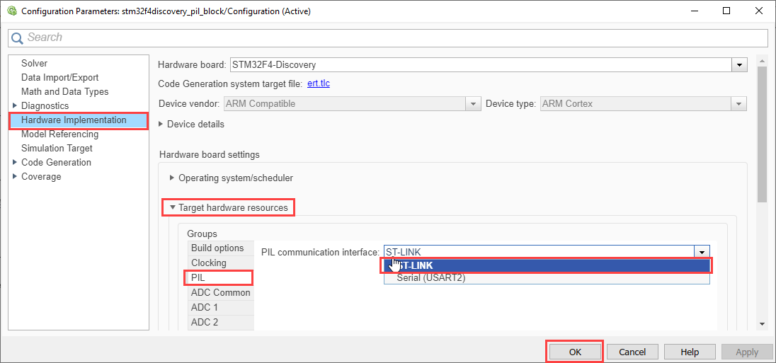
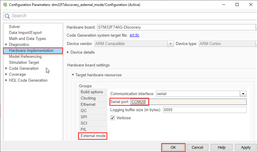
For STM32F746G-Discovery or STM32F769I-Discovery, in Configuration Parameters > Hardware Implementation > Target Hardware Resources > PIL > COM Port enter the COM port of the serial interface on Windows. Follow steps 3 and 4 to configure the COM port.
2. For STM32F4-Discovery, if you choose to use the serial communication interface, follow the hardware setup instructions below:
Connect ground pin of the USB TTL-232 cable to one of the GND pins on the STM32F4-Discovery board
Connect the RX pin of the USB TTL-232 cable to PA2 pin on the STM32F4-Discovery board
Connect the TX pin of the USB TTL-232 cable to PA3 pin on the STM32F4-Discovery board
Connect the USB side of the USB TTL-232 cable to your host computer
Power on your board by connecting a USB type A to Mini-B cable to the STM32F4-Discovery board
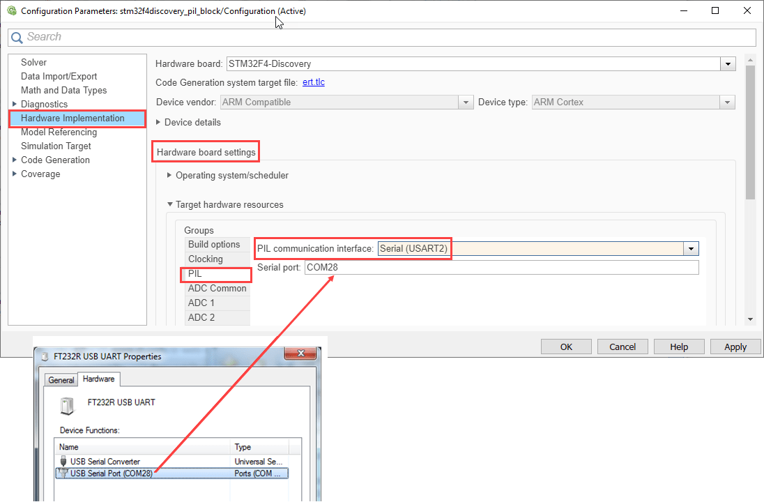
3. Once you complete the above steps, a new serial / COM port should be available for use on your host computer. To find the COM port associated with your adapter cable, follow the steps below:
Open Devices and Printers in Windows®
Double-click the entry for your USB TTL-232 adapter device
In the device properties dialog, click the Hardware tab, and then click the Properties button
Click the Port Settings tab
4. Copy the COM port number to the Simulink model as shown.
Verifying the Generated Code for a Subsystem Using a PIL Block
This example shows how to use a PIL block for subsystem code verification. With this approach:
You can verify the code generated for a subsystem
You must provide a test harness model to supply a test vector or stimulus inputs
You must swap your original subsystem with a generated PIL block; you should be careful to avoid saving your model in this state as you would lose your original subsystem
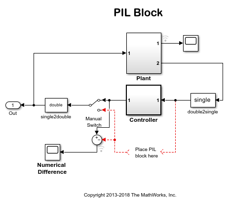
1. Open the stm32f4discovery_pil_block model. This model is configured for the STM32F4-Discovery target. You can run the model for STM32F746G-Discovery or STM32F769I-Discovery target, by changing the Hardware board to STM32F746G-Discovery or STM32F769I-Discovery in the Configuration Parameters > Hardware Implementation pane.
The objective here is to create a PIL block out of the Controller subsystem that you will run on the STM32 Discovery board.
2. Choose a PIL communication interface by following the steps in Task 1 above.
3. Enable PIL by following Task 1 - Step 2 of the Code Verification and Validation with PIL example.
4. Create a PIL block for the Controller subsystem by following Task 1 - Step 3 of the Code Verification and Validation with PIL example.
5. Run PIL simulation by following Task 1 - Step 4 of the Code Verification and Validation with PIL example.
6. In case of STM32F4-Discovery, once you start the PIL simulation, a new OpenOCD session is launched. OpenOCD is used to download the code to the processor. If ST-LINK is selected as the PIL communication interface, OpenOCD will also be used to perform host to target communication during PIL simulations. On the STM32F746G-Discovery or STM32F769I-Discovery, the generated executable is copied to the drive letter in Windows of the board.
7. You can switch between the original and PIL block subsystems by double clicking on the Manual Switch block. Double click on the Numerical Differences block to see the difference between the simulated Controller subsystem and the PIL block running on the STM32 Discovery board.
Verifying Referenced Model Code Using PIL
This example shows how to verify the generated code for a referenced model by running a PIL simulation. With this approach:
You can verify code generated for referenced models
You must provide a test harness model to provide a test vector or stimulus inputs
You can easily switch a Model block between normal and PIL simulation mode
1. Open the stm32f4discovery_model_pil_block model. This model is configured for STM32F4-Discovery target. You can run the model for STM32F746G-Discovery or STM32F769I-Discovery target, by changing the Hardware board to STM32F746G-Discovery or STM32F769I-Discovery respectively in the Configuration Parameters > Hardware Implementation pane. The model contains two Model blocks that both point at the same referenced model. Note, that the Hardware board change has to be made in the reference model also by double clicking on CounterTypeA or CounterTypeB to open the referenced model and following the steps above. You will configure one of the Model blocks to run in PIL simulation mode and the other in normal mode.

2. Choose a PIL communication interface by following the steps in Task 1 above.
3. Configure and run CounterA Model block in PIL simulation mode by following Task 2 - Step 2 of the Code Verification and Validation with PIL example.
4. When the model starts running, Scope1 displays the PIL simulation output running on the STM32 Discovery board while Scope2 shows the normal mode simulation output.
Verifying Top Model Code Using PIL
This example shows how to verify the generated code for a model by running a PIL simulation. With this approach:
You can verify code generated for a top model
You must configure the model to load test vectors or stimulus inputs from the MATLAB workspace
You can easily switch the entire model between normal and PIL simulation mode
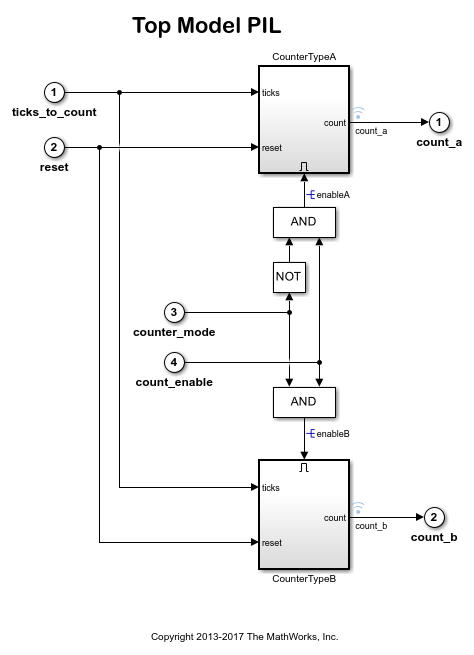
1. Open the stm32f4discovery_top_model_pil model. This model is configured for the STM32F4-Discovery target. You can run the model for STM32F746G-Discovery or STM32F769I-Discovery target, by changing the Hardware board to STM32F746G-Discovery or STM32F769I-Discovery respectively in the Configuration Parameters > Hardware Implementation pane.
2. Choose a PIL communication interface by following the steps in Task 1 above.
3. Run the top model PIL simulation by following Task 3 - Step 2 of the Code Verification and Validation with PIL example.
4. When the PIL simulation is completed, a logsOut variable is created in the base workspace. The logsOut data contains PIL simulation results. You can access the logged data for signals count_a and count_b using the following commands:
count_a = get(logsOut,'count_a');
count_a.Values.Data
count_b = get(logsOut,'count_b');
count_b.Values.Data
Monitor and Tuning Using STM32F746G-Discovery or STM32F769I-Discovery Board
When you are prototyping and developing algorithms, it is useful to monitor signals and tune parameters while the algorithms are running on the hardware. The Simulink Monitor & Tune feature enables this capability. The STM32F746G-Discovery and STM32F769I-Discovery boards support Monitor and Tuning over Universal Measurement and Calibration Protocol (XCP).
Simulink provides these additional features for the targets that support XCP:
Dashboard objects such as Slider and Dashboard Scope. For more information, see Dashboard.
Simulation Data Inspector (SDI) for visualizing the logged signals. For more information, see Simulation Data Inspector.
The STM32F4-Discovery board does not support XCP. For information about using the STM32F4-Discovery board, see External Mode Using the STM32F4-Discovery Board.
In this task, you will run the stm32f7discovery_external_mode model.
1. Open the stm32f7discovery_external_mode model.

2. This example model has one signal selected for logging. To select additional signals, right-click the required signal and select the Log Selected Signals option.
3. Specify the COM Port according to the instructions in the Choosing a Communication Interface for PIL Simulation section.
4. Go to Hardware tab, and click Monitor & Tune to configure the model for simulation.

At this point, your model is running on the STMicroelectronics Discovery board and communicating with Simulink from Monitor & Tune. You can select the Simulation > Data Inspector button to view the logged signals, as shown.

5. You can tune the parameters and visualize the signals selected for logging by:
Double-clicking the Manual Switch block to change the input source.
Using the Slider to change the signal gain.
Double-clicking the Scope block to view the simulation results.
The model is running in real-time on the target while performing these actions.
6. Stop Monitor & Tune simulation by clicking the Stop button, as shown.

Stopping the Monitor & Tune simulation terminates the execution of the code running on the STM32 Discovery board.
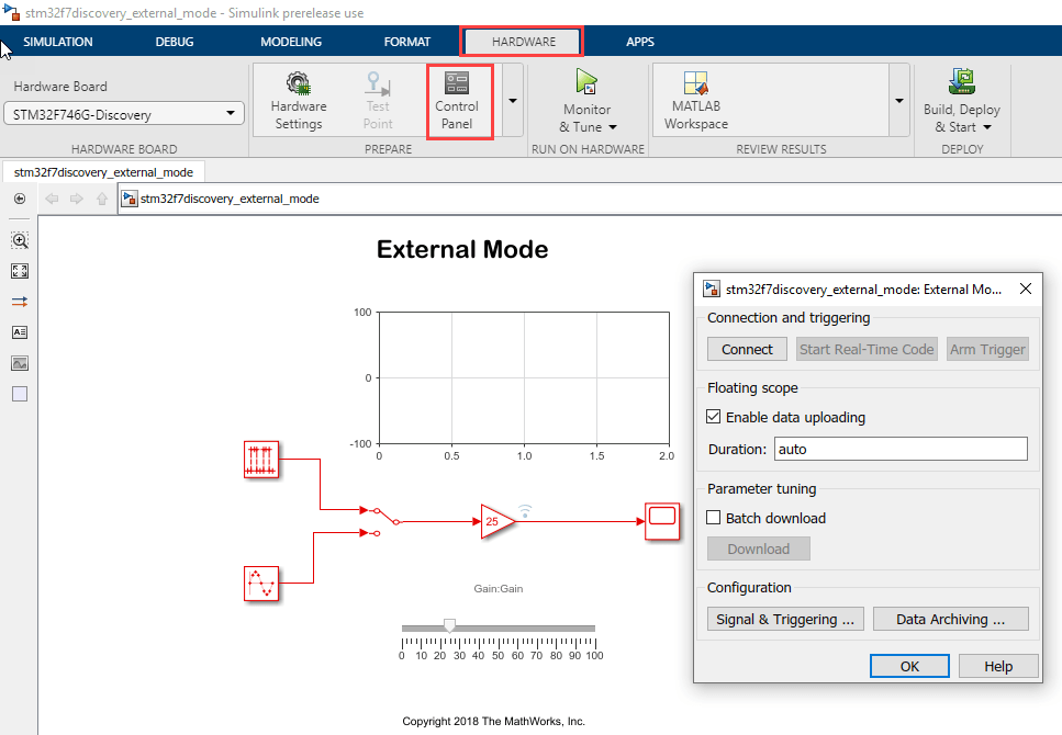
Note: At any point during the course of the simulation, you can open the External Mode Control Panel, as shown. The Hardware > control panel provides more options, such as the ability to connect or disconnect to the target without terminating the execution of the generated code.
Limitations
Running Monitor & Tune over XCP has a few limitations. For a detailed list, see External Mode Simulation by Using XCP Communication.
Migrate to STM32CubeMX Workflow
To migrate to the STM32CubeMX workflow for STM32 processor based boards, use the Code Verification and Validation with PIL for STMicroelectronics STM32 Processors Based Boards example to implement the equivalent STM32CubeMX workflow.