Getting Started with Connected IO on STM32 Processor Based Boards
This example shows how to use Connected IO in Embedded Coder® Support Package for STMicroelectronics® STM32 Processor. It illustrates how to progressively add blocks and use Connected IO to read and write values to and from target hardware.
Connected IO creates a communication interface that enables the Simulink model and the IO Server to communicate with each other. The model communicates with the hardware and no code generation is required.
Simulation with Connected IO is an intermediate step in the Model-Based Design workflow that bridges the gap between simulation and code generation by enabling Simulink to communicate with the hardware before deploying the model on the hardware.
Prerequisite
Complete the following tutorials:
Required Hardware
To run this example you need the following hardware:
STMicroelectronics STM32 Processor based board. This example uses STMicroelectronics NUCLEO-F429ZI board.
Micro USB cable
Hardware Connections
Connect the GPIO pins to two of the ADC channels.
Connect the other ADC channel to the PWM output channel. For information on using ADC channels see Using the Analog to Digital Converter Block to Support STMicroelectronics STM32 Processor Based Boards. For information on using PWM outputs, see PWM Output.
Note:
The GPIO pins will toggle with a pulse having a one-second ON time and one-second OFF time.
The pulses to the GPIO pins will be
180degrees out of phase with each other.
Task 1 - Create a STM32CubeMX Project to Configure Peripherals
Support for STM32 Processor Based Board with Simulink uses STM32CubeMX graphical tool. STM32CubeMX tool is a graphical interface that you can use to configure peripherals of STM32 processors and generate peripheral initialization code for the STM32 processors that you select. For more information on the STM32CubeMX tool, see STM32CubeMX overview.
You can choose an existing STM32CubeMX project or create a new one. You can launch the project from your Simulink model. Follow the following instructions to create a model to support your STM32 processor based board:
1. Open the Modeling tab and press CTRL+E to open the Configuration Parameters dialog box. Go to Hardware Implementation > Hardware board.
2. Select STM32 Processor Based board.
3. Go to Build options and click Browse to select an existing STM32CubeMX project file.
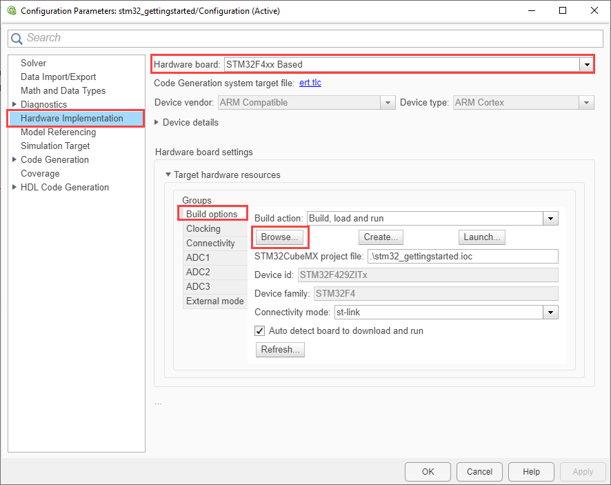
4. Click Create to create a new STM32CubeMX project file.
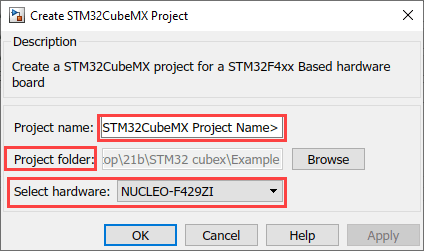
Provide a project name with an .ioc extension.
Browse to the desired folder location and save the project.
Select the STM32 hardware and click Apply and OK.
You can also create a new project by selecting custom STM32 Processor Based hardware.
Task 2 - Configure STMicroelectronics STM32CubeMX Project in Simulink
In this task, configure the target model to use Connected IO.
1. Open the gettingStartedConnectedIO.
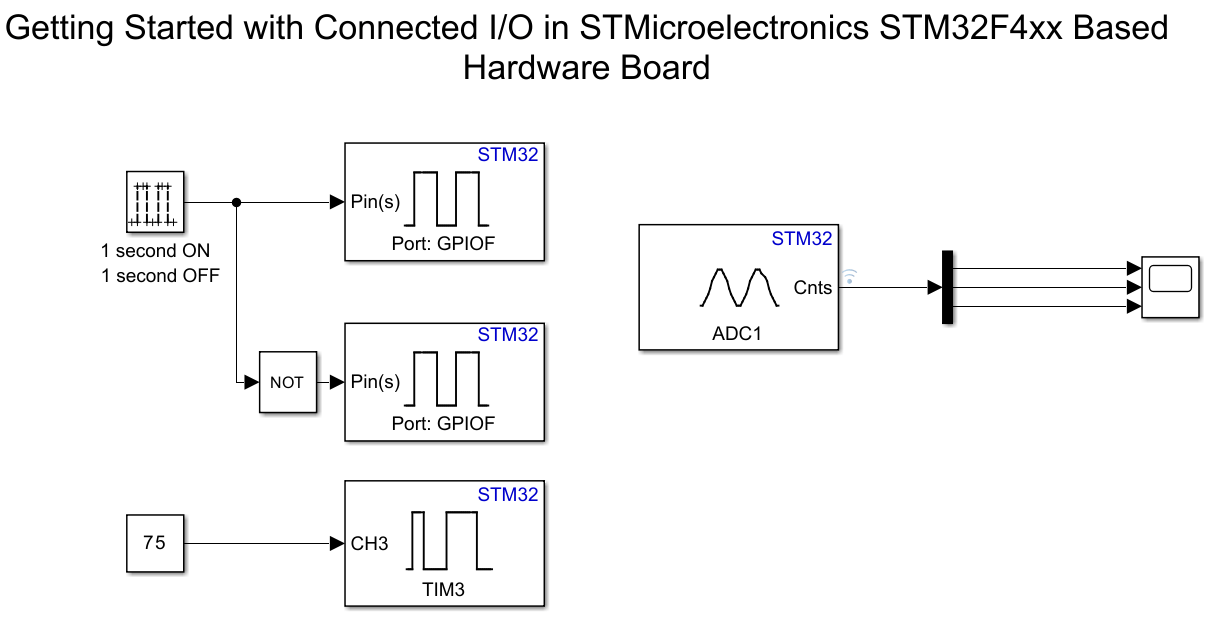
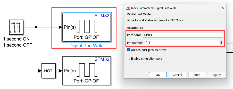
2. Configure the GPIO block. Double-click the block to open the block parameter dialog box.
Input pin 3 connected to pin 3 of the GPIOB port.
3. Create a new STM32CubeMX project or browse to an existing STM32CubeMX project. Launch the STM32CubeMX project in the STM32CubeMX tool. For details, see Task 1.
4. Configure the following configurations in your selected STM32CubeMX project.

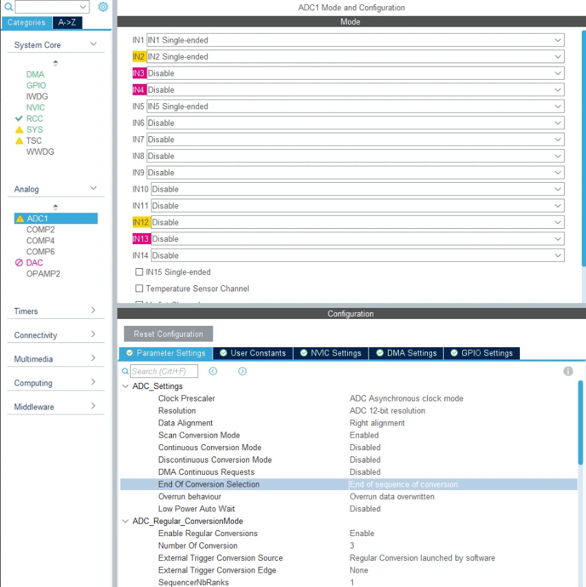
5. ADC configuration
Navigate to Pinout & Configuration > Analog and configure the ADC settings as shown in this image.
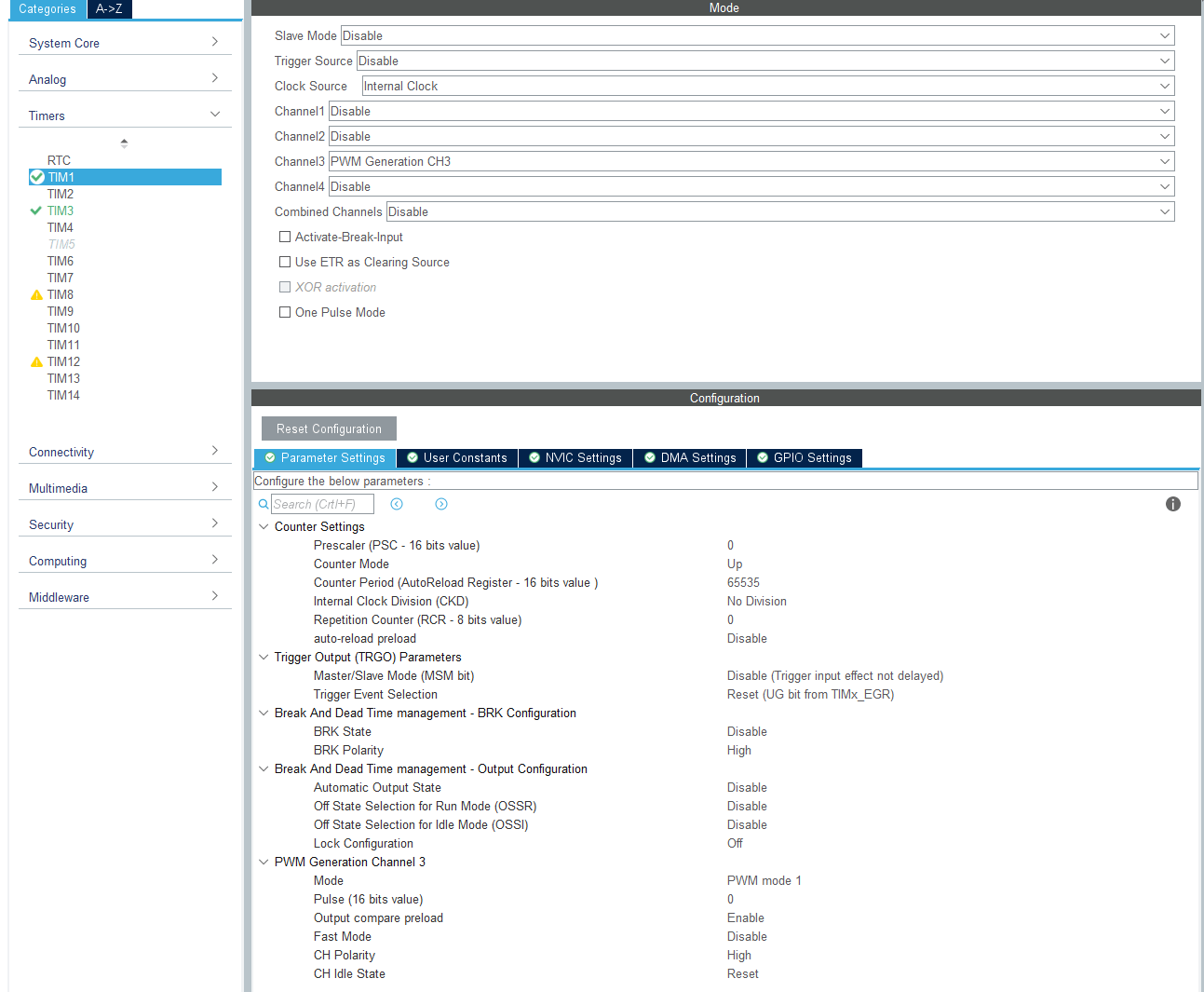
6. Timer Configuration
Navigate to Pinout & Configuration > Timers and configure the Timer settings as shown in this image.
7. GPIO configuration
Navigate to Pinout & Configuration > System Core and configure the GPIO settings.
Select the Set the repetition counter after counter is enabled parameter to update the event when the timer counter overflows.

8. In your STM32CubeMX project, ensure to perform the following configurations:
Enable Do not generate the main() under Project Manager > Project.
Disable Generate under root under Project Manager > Project.
Under Project Manager > Advanced Settings > Driver Selector, select low level (LL) drivers for the peripherals.
Under Project Manager > Advanced Settings > Generate Functions Calls, deselect Do Not Generate Function Calls for all the peripheral initialization function calls.
Under Project Manager > Advanced Settings > Generate Function Calls, deselect Visibility (Static) for all the peripheral initialization function calls.
Save the project.
Task 3 - Configure and Run Simulink Model in Connected IO Mode
Perform these steps to configure and run your model in Connected IO mode.
1. Start MATLAB®. From the MATLAB toolstrip, click Simulink.
2. Click the Blank Model template. The Simulink Editor opens.
3. Press Ctrl+E to open the Configuration Parameters dialog box. Then, select the STM32 processors hardware board by navigating to Hardware Implementation > Hardware board.
4. Add a GPIO Block.
Connect a pulse generator to the GPIO block, configured to produce a one-second ON and one-second OFF pulse.
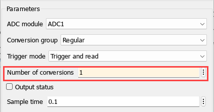
5. Add an ADC Block.

Double-click the ADC block to open the block parameters dialog box. Set the Number of conversions parameter to
1.
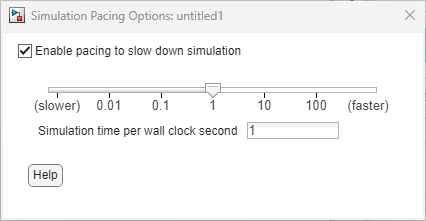
6. Enable Simulink Pacing.
In the Simulink® Toolstrip, on the Simulation, Debug, or Modeling tab, click the Run button arrow. Then, select Simulation Pacing. Select Enable pacing to slow down simulation and adjust the pacing time value to
1second.
7. Run the Model in Connected IO.
On the Hardware tab of the Simulink model, in the Mode section, select Connected IO.

Click Run with IO to start the model in Connected IO mode. If the required libraries are not available on the target hardware, the IO server will be flashed onto the target for the first time.

Watch the output of the ADC block toggle in synchronization with the pulse generator signal.
8. Add Another GPIO Block.

Attach another pulse generator to this new GPIO block, set to produce a one-second ON and one-second OFF pulse. Use a NOT block to invert the signal, ensuring the input pulses to the two GPIO blocks are 180 degrees out of phase.
9. Modify the ADC Block.
Increase the number of conversions in the ADC block to
2.
10. Run the model again in Connected IO.
Observe the outputs of the ADC block toggling in sync with the pulses supplied to each GPIO block.
11. Add a PWM Output block.

Double-click the PWM Output block to open the block parameters dialog box. Activate channel 3 on the TIMER block and define the Duty cycle input for the TIMER block as a Percentage.

12. Modify the ADC block again.
Update the number of conversions in the ADC block to
3.
13. Run the model again in Connected IO.
Execute the model once more in Connected IO.
Observe the output of the ADC block varies according to the duty cycle set on the PWM Output block.
You can also use the preconfigured gettingStartedConnectedIO model to try the above steps in Connected IO.