Voltage Mode Control of DC-DC Buck Converter and Boost Converter Using STMicroelectronics STM32 Processor
This example shows how to implement a DC-DC buck converter or Boost Converter control system using the B-G474E-DPOW1 Discovery kit for Embedded Coder® Support Package for STMicroelectronics® STM32 Processors.
Using this example, you can:
Verify that the closed-loop proportional-integral (PI) control algorithm optimally regulates the buck converter output voltage on the B-G474E-DPOW1 Discovery kit (control algorithm executes at 200KHz sampling rate).
Activate and de-activate the onboard embedded loads to verify if the PI controller can compensate for any load variations and maintain the desired output voltage for buck converter. As onboard embedded loads are rated to 5V, external loads needs to be connected for boost converter.
Perform data logging at a high sample rate using the two-model approach.
Introduction
Buck Converter
The B-G474E-DPOW1 Discovery kit contains a synchronous buck converter power stage. A simplified schematic of the power stage for a synchronous buck converter is shown here.
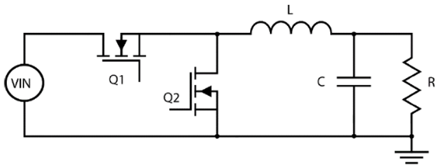
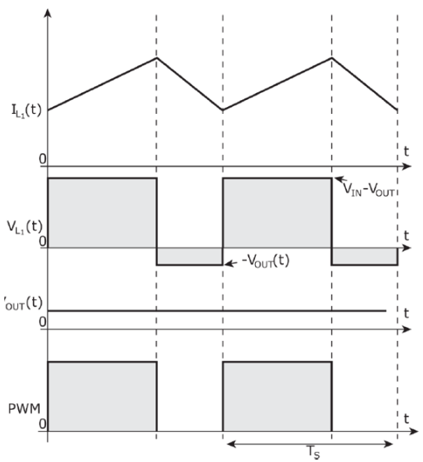
At the beginning of the switching period, the PWM of the top switch (Q1) is set HIGH and the bottom switch (Q2) is set LOW.
This turns on MOSFET-Q1 and turns off MOSFET Q2. With the Q1 switch conducting, the current through the inductor L1 begins increasing linearly. At the end of the high-side duty cycle, the switch Q1 is turns off.
A dead time is inserted between the high-side and low-side PWM for switches Q1 and Q2 to prevent shoot-through, where both switches are partially on at the same time causing a large current to flow through Q1 and Q2 and can damage the MOSFETs. When this dead time has elapsed the low-side PWM for the Q2 turns to high setting which turns on Q2. At this time, the inductor acts to continue the flow of current and the current now flows through Q2. The current through the inductor begins decreasing linearly. This switching action is described here in the buck converter waveforms.
This figure shows the overall design with the peripherals to achieve the voltage mode control of the buck converter on the B-G474E-DPOW1 Discovery kit.
Boost Converter
The B-G474E-DPOW1 Discovery kit contains a synchronous boost converter power stage. A simplified schematic of the power stage for a synchronous boost converter is shown below.
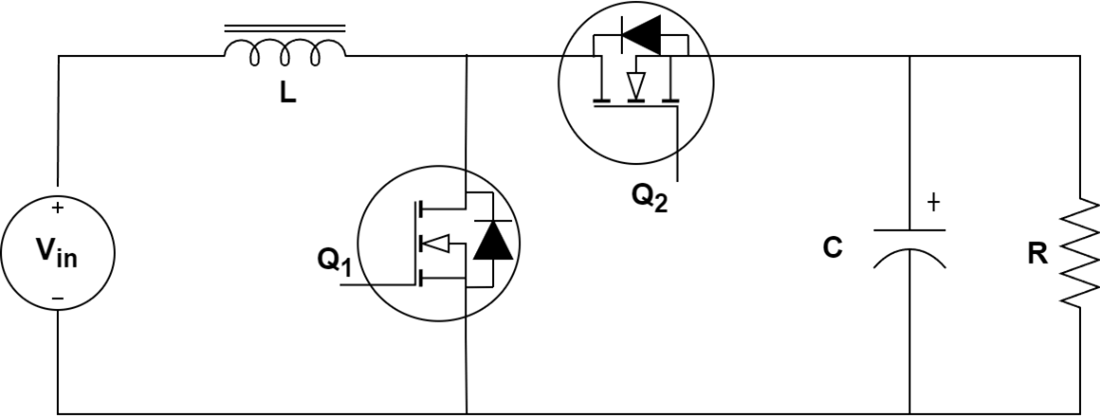
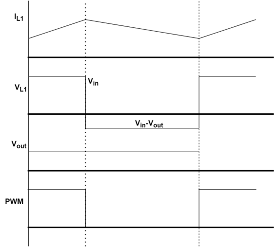
At the beginning of the switching period, the PWM of the bottom switch (Q1) is set HIGH and the top switch (Q2) is set LOW. This turns on MOSFET-Q1 and turns off MOSFET Q2. With the Q1 switch conducting, the current through the inductor L1 begins increasing linearly. At the end of the low-side duty cycle, the switch Q1 is turns off.
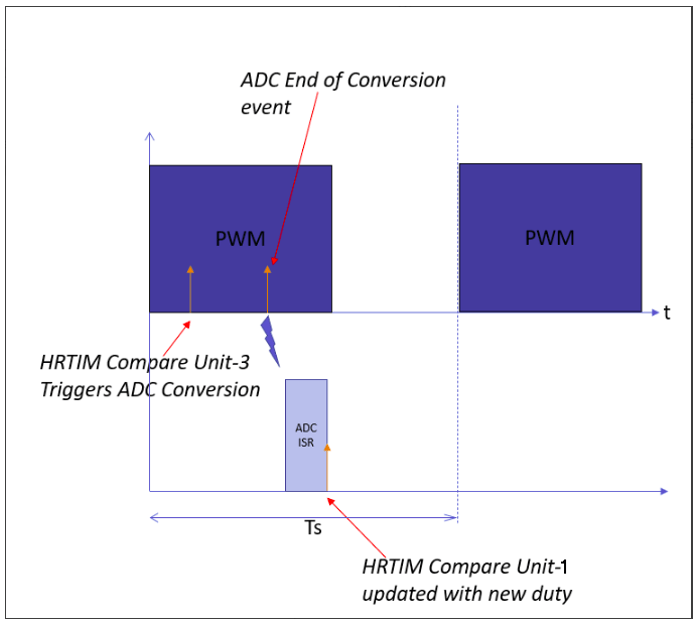
The sampling of the ADC module is triggered by the HRTIM module, in this case by comparing unit 3, which is set to a number of HRTIM ticks after the beginning of the switching period to avoid switching noise corrupting the sample. Once the sampling and conversion are complete, the ADC triggers the end of conversion interrupt to the CPU. Within this ISR the PI controller can compute the correction duty and update the HRTIM compare unit 1. The new duty applies from the next switching cycle of the PWM.
Prerequisites
Required Hardware
To run this example you need the following hardware:
Micro-USB cable for ST-LINK in-circuit debugger and programmer
B-G474E-DPOW1 Discovery kit
5V buck converter input power via the USB-C cable
External load for Boost Converter
Required STMicroelectronics Product
STM32CubeMX v6.4.0 along with STM32Cube firmware library for G4 (v1.2.0 or later)
Hardware Connection
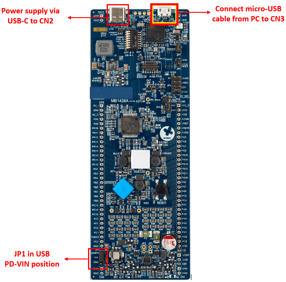
Configure the following connections on B-G474E-DPOW1 Discovery kit.
Available Models
Model
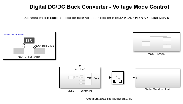
Using this model you will learn how to regulate the synchronous buck converter power stage as available on the onboard B-G474E-DPOW1 Discovery kit in voltage-mode control and its implementation using the STMicroelectronics® ARM® Cortex®-M4 core-based STM32G474RET6 microcontroller.
Target Model with Hardware Interrupt block triggers the PI controller Subsystem at
200KHz.The
VMC_PI_Controllerreads the current output voltage and compares it to the voltage setpoint.The error generated is used by PI controller to compute the correction signal.
The new computed duty is programmed into the HRTIM compare register.
The Vout is later sent to the host model for signal logging.
Configure and Run Digital DC/DC Buck Converter - Voltage Mode Control Model
1. Open the stm32g474_DCDC_Buck.slx model. This model is configured for STM32G4xx Based hardware.
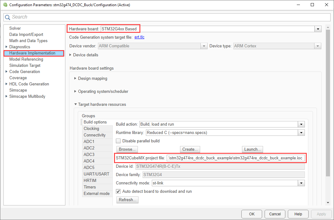
2. To run the model on other STM32 processors, first press Ctrl+E to open the Configuration Parameters dialog box. Then, select the STM32G4xx Based hardware board by navigating to Hardware Implementation > Hardware board.
3. Configure the peripherals in the model as described in peripherals configurations section. You can use the same parameter values if you want to run this example for other hardware boards.
Repeat the same steps for the stm32g474_DCDC_Boost.slx model and select the stm32g474re_dcdc_boost_example.ioc in the Model Configuration.
Peripheral Configurations
Set the peripheral block configurations for this model. Double-click the blocks to open block parameter configurations. You can use the same parameter values if you want to run this example on other hardware boards. The following configuration are shown for Buck converter model. You can perform the similar configurations for Boost Converter stm32g474_DCDC_Boost.slx model.
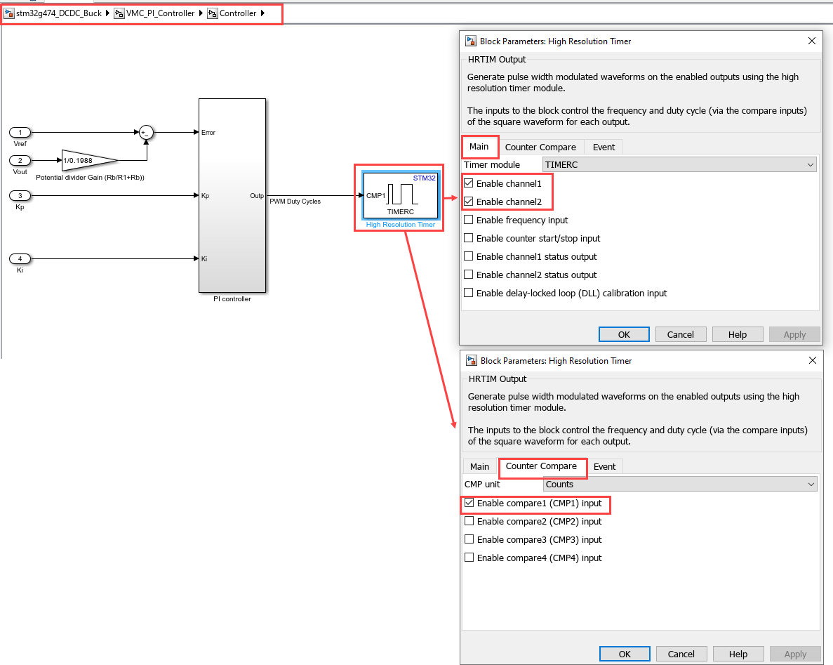
High Resolution Timer block
Configure the HRTIM block to enable channel and counter compare. For Boost Converter, configure the Timer as Timer D
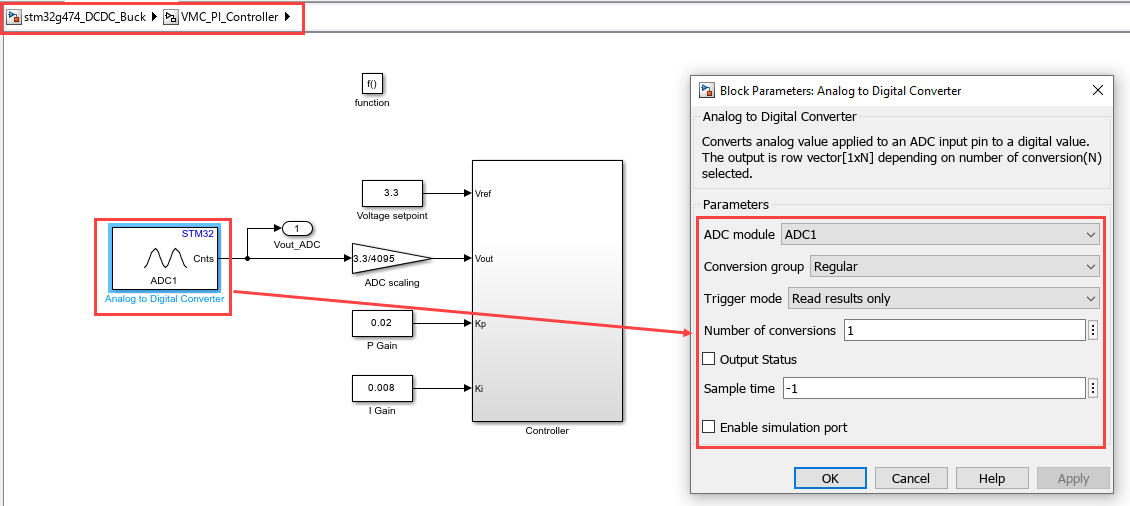
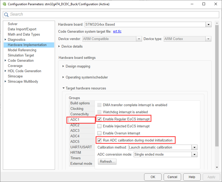
ADC block
Configure the ADC block and configuration parameters as shown here.
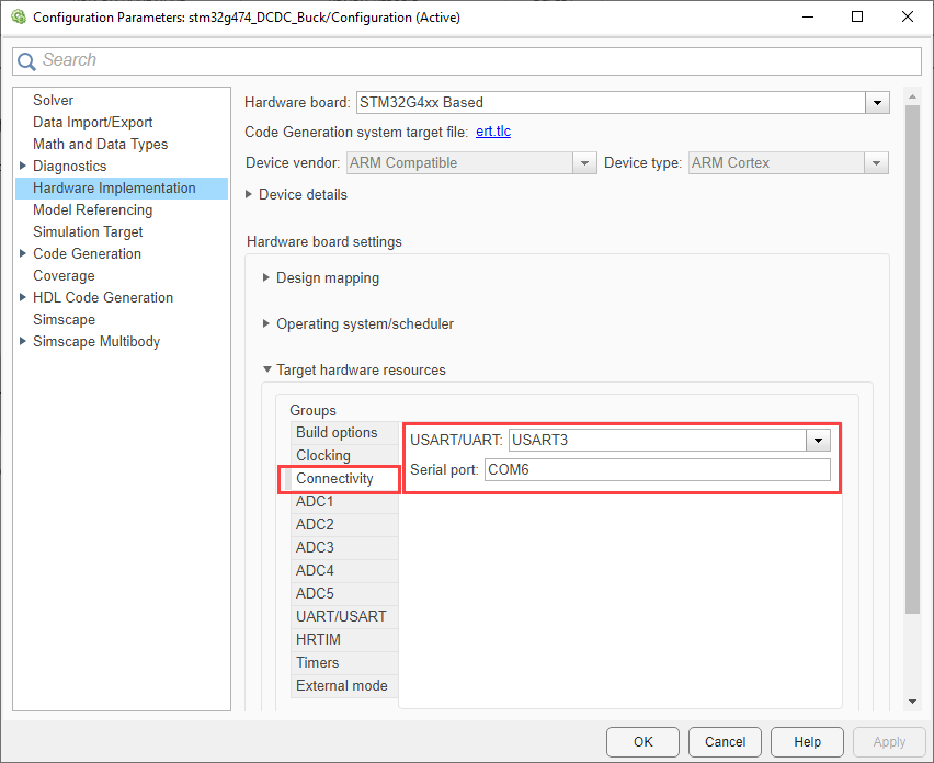
USART/UART
Configure USART3 for Host-Target communication. Ensure to update the COM port.
STM32CubeMX Configuration
Click Launch from Configuration Parameters to open the selected STM32CubeMX project in the STM32CubeMX tool.
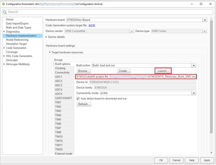
Open STM32CubeMX project and configure the following.
STM32CubeMX Project manager. For more information, see STM32CubeMX Project Manager Configuration.
STM32CubeMX Clock Configuration. For more information, see STM32CubeMX Clock Configuration.
STM32CubeMX Pin Configuration. For more information, see STM32CubeMX Pin Configuration.
Generate Code and Load on Hardware Board from Simulink Model
1. To generate the code for the model, press Ctrl+B or click Build, Deploy & Start.

2. Follow the build process by opening the diagnostic viewer using the link provided at the bottom of the model canvas.
Monitor Signals on Host Computer
Configure and Run Model on Host Computer
1. On the host computer, browse to Device Manager > Ports (COM & LPT) to find the COM port.
2. Set the parameter Port of the following blocks in the stm32_DCDC_Buck_host_model model to match the COM port of the host computer:
stm32_DCDC_Buck_host_model > Serial Configuration
stm32_DCDC_Buck_host_model > Serial Receive
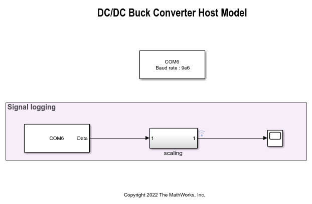
3. Click the Run button on the Simulation tab to run the host model.

4. Observe the signal logging in the Host model to read the Vout as transmitted from the target model. The following hardware result shown are for Buck Converter.
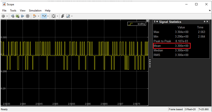
Note: If the host and the target are not communicating in real time, try closing the Scope block and run the simulation of the host model. You might encounter a lag in uploading the data in the Scope block if you have other applications running simultaneously in your machine.
Enable Active Load
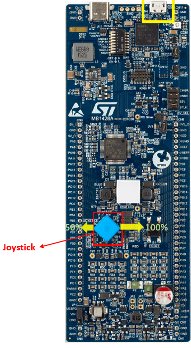
Onboard joystick can be used to enable the active loads and monitor the impact on the voltage regulation.
Press the left side of the joystick for
50%load and the right side for100%load as shown.Onboard loads are made available only in the buck converter model via joystick.
The available loads are rated for 5V, so for higher voltage user need to use an external load.
Other Things to Try
Run the example on the STM32F7xx based board and analyze the results.