Design Techniques to Optimize Models for Efficient Code Generation
Use the Model Advisor to Optimize a Model
You can use the Model Advisor to analyze a model for code generation and identify aspects of your model that impede production deployment or limit code efficiency. You can select from a set of checks to run on a model's current configuration. The Model Advisor analyzes the model and generates check results providing suggestions for improvements in each area. Most Model Advisor diagnostics do not require the model to be in a compiled state; those that do are noted.
Before running the Model Advisor, select the target you plan to use for code generation. The Model Advisor works most effectively with ERT and ERT-based system target files.
For more information on using the Model Advisor, see Run Model Advisor Checks. For more information about the checks, see Model Advisor Checks.
Design Techniques to Optimize a Model for Code Generation
You can apply the following techniques to optimize a model for code generation:
For Embedded Coder® users, if your application uses only integer arithmetic, clear the Support floating-point numbers parameter in the Software environment section of the Interface pane so that the generated code does not contain floating-point data or operations. When this parameter is cleared, an error is raised if noninteger data or expressions are encountered during code generation. The error message reports the offending blocks and parameters.
Disable the Configuration Parameters > Code Generation > Interface > Advanced parameters > MAT-file logging parameter. Deselecting this parameter eliminates extra code and memory usage for initializing, updating, and cleaning-up logging variables. In addition, the code generated to support MAT-file logging invokes
malloc, which can be undesirable for your application.Use the Upgrade Advisor to upgrade older models (saved by prior versions or the current version) to use current features. For details, see Model Upgrades.
Before building, set optimization flags for the compiler (for example,
-O2forgcc,-Otfor the Microsoft® Visual C++® compiler).Directly inline C/C++ S-functions into the generated code by writing a TLC file for the S-function. For more information, see Use S-Function Target for Model or Subsystem and see Inline C MEX S-Functions.
Use a Simulink® data type other than
doublewhen possible. The available data types areBoolean, signed and unsigned 8-, 16-, and 32-bit integers, and 32- and 64-bit floats (adoubleis a 64-bit float). For more information, see About Data Types in Simulink. For a block-by-block summary, clickshowblockdatatypetableor type the command in the Command Window.For tunable block parameters that you configure to store in memory in the generated code, you can match parameter data types with signal data types to eliminate unnecessary typecasts and C shifts. Where possible, store parameter values in small integer data types. See Parameter Data Types in the Generated Code.
Remove repeated values in lookup table data.
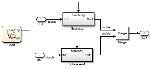
Use the Merge block to merge the output of signals wherever possible. This block is particularly helpful when you need to control the execution of function-call subsystems with a Stateflow® chart. The following model shows an example of how to use the Merge block.

When more than one signal connected to a Merge block has a non-
Autostorage class, all non-Autosignals connected to that block must be identically labeled and have the same storage class. When Merge blocks connect directly to one another, these rules apply to the signals connected to any of the Merge blocks in the group.
Design Techniques to Optimize Stateflow Objects for Code Generation
Be Explicit About the Inline Option of a Graphical Function
When you use a graphical function in a Stateflow chart, select
Inline or
Function for the property
Function Inline Option.
Otherwise, the code generated for a graphical function may
not appear as you want. For more information, see Specify Properties of Graphical Functions (Stateflow).
Avoid Using Multiple Edge-Triggered Events in Stateflow Charts
If you use more than one trigger, you generate multiple code statements to handle rising or falling edge detections. If multiple triggers are required, use function-call events instead. For more information, see Activate a Stateflow Chart by Sending Input Events (Stateflow).
Combine Input Signals of a Chart Into a Single Bus Object
When you use a bus object, you reduce the number of parameters in the parameter list of a generated function. This guideline also applies to output signals of a chart. For more information, see Define Stateflow Buses (Stateflow).
Use Charts with Discrete Sample Times
The code generated for discrete charts that are not inside a triggered or enabled subsystem uses integer counters to track time instead of Simulink provided time. This allows for more efficient code generation in terms of overhead and memory, as well as enabling this code for use in software-in-the-loop (SIL) and processor-in-the-loop (PIL) simulations.