Generate Code for Variant Source and Variant Sink Blocks
This example explains how to generate code for a specific implementation of a component represented using Variant Source and Variant Sink blocks. You can customize your code to include one or multiple implementations of the component.
The Variant Source and Variant Sink blocks are inline variant blocks that allow you to include multiple implementations, or variants, of a component in a single model. Each variant of the component connected to the input or output ports of the Variant Sink and Variant Source block is called a variant choice. Similarly, each variation of the component connected to the output ports of the Variant Sink block is also referred to as a variant choice. Only one variant choice of an inline variant block can be active during model simulation. You can generate code that includes one or multiple choices of inline variant blocks. For more information, see Propagate Variant Conditions to Define Variant Regions Using Variant Source and Variant Sink Blocks.
Prerequisites
We recommend completing the Propagate Variant Conditions to Define Variant Regions Using Variant Source and Variant Sink Blocks to learn more about how to use Variant Source and Variant Sink blocks in Simulink®.
Represent Variant Choices in Variant Source and Variant Sink Blocks
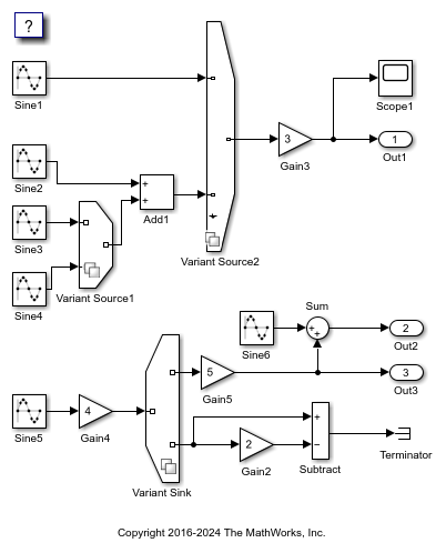
Open the model slexVariantSourceAndSink.
The slexVariantSourceAndSink model contains two Variant Source blocks, Variant Source1 and Variant Source2, and a Variant Sink block. The variant conditions at the input and output ports of the Variant Source and the Variant Sink blocks determine the activation and deactivation of the blocks connected to them.
model = "slexVariantSourceAndSink";
open_system(model);
Specify Variant Controls for Variant Choice Selection
Each variant choice in the model is associated with a variant control. Variant controls determine which variant choice is active. By changing the value of a variant control, you can switch the active variant choice. While each variant choice is associated with a variant control, only one variant control can evaluate to true. When a variant control evaluates to true, Simulink activates the variant choice that corresponds to that variant control. For more information, see Introduction to Variant Controls.
1. Right-click the variant badge on a variant block and select Block Parameters. In this example, each variant choice of the variant blocks is associated with variant control variables V and W. The variables V and W are Simulink.Parameter
2. In the MATLAB™ Command Window, set the value of V to 1 and W to 1. Simulate the model. During simulation, the variant control expressions V == 1 and W == 1 evaluate to true, activating the first input ports of the Variant Source2 and Variant Sink blocks.
V.Value = 1;
W.Value = 1;
sim(model);
3. Set the value of V to 2 and W to 1. Simulate the model again. During simulation, V == 2 and W == 1 evaluate to true, activating the first input port of the Variant Source1 block and the second input port of the Variant Source2 block.
V.Value = 2;
W.Value = 1;
sim(model);
For information on the variant conditions that activate the Variant Source1 and the Variant Sink blocks, see Propagate Variant Conditions to Define Variant Regions Using Variant Source and Variant Sink Blocks.
This mechanism allows you to swap the active and inactive choices for the variant blocks without modifying the model structure, making the model flexible and adaptable to different scenarios.
If Simulink.Parameter
Configure Model to Generate Code
By default, Simulink supports generating code only for a specific choice of a variant block. You can customize your model to generate code for multiple choices of the block using the Variant activation time parameter. The Variant activation time parameter enables you to set the active variant choice at intermediate stages to improve the speed of simulation and allows you to reuse the artifacts from the previous runs in code generation workflows. It also enables you to analyze variant choices for incompatibilities, such as data type and dimension mismatches, prior to simulation and code generation. For more information, see Activate Variant During Different Stages of Simulation and Code Generation Workflow.
1. To generate code for the first inputs of the Variant Source2 and Variant Sink blocks, check these settings:
The values of the variant control variables
VandWare set to1.
V.Value = 1;
W.Value = 1;
The Variant activation time parameter of the blocks is set to
update diagram.
set_param(model+"/Variant Source2","VariantActivationTime","update diagram");
set_param(model+"/Variant Sink","VariantActivationTime","update diagram");
2. In the Apps tab of the toolstrip, navigate to Simulink Coder or Embedded Coder. In the C code tab, select Build > Generate code. Observe that the generated code includes the logic only for the active variant choice blocks. Alternatively, enter this command in the Command Window.
slbuild(model)
### Starting build procedure for: slexVariantSourceAndSink
### Successful completion of build procedure for: slexVariantSourceAndSink

Build Summary

Top model targets built:

Model                     Action                        Rebuild Reason
==========================================================================================================
slexVariantSourceAndSink  Code generated and compiled.  Code generation information file does not exist.

1 of 1 models built (0 models already up to date)
Build duration: 0h 0m 10.249s
Use of VariantMerge Blocks
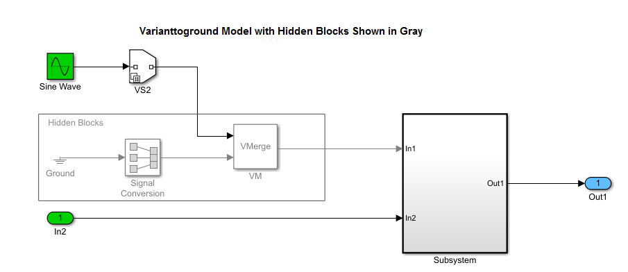
For modeling patterns in which a root Inport block connects to a variant block with one variant choice, Simulink inserts a hidden block combination of a Ground block, Signal Conversion block, and VariantMerge block. If the variant choice evaluates to false, this block combination produces an output of 0.0.
For example, the model Varianttoground contains a Variant Source block with one variant choice. When the variant control SYSCONST_A == 6 evaluates to true, the input to Subsystem is a sine wave. When SYSCONST_A == 6 evaluates to false, the input to Subsystem is 0.0.
The varianttoground.c fiele contains this code:
* Sin: '<Root>/Sine Wave' incorporates:
  *  SignalConversion generated from: '<Root>/Subsystem'
  */
#if SYSCONST_A == 6
Varianttoground_B.VM_Conditional_Signal_Subsystem_0 = sin
  (Varianttoground_M->Timing.t[0]);
#else
/* SignalConversion generated from: '<Root>/Subsystem' */
Varianttoground_B.VM_Conditional_Signal_Subsystem_0 = 0.0;
#endif
/* End of Sin: '<Root>/Sine Wave' */
The comments in the generated code indicate the presence of the hidden signal conversion block. In the hyperlinked comments, you can trace to the original block in the model that triggered the insertion of the hidden block. The code does not contain a comment for the VariantMerge block because this block does not have associated generated code. The VariantMerge block is used internally and is not in the Simulink library.
Review Generated Code
In the C Code tab of the toolstrip, select Open Report.
Locate and select the slexVariantSourceAndSink.c file from the left pane. Observe that the calls to the step and initialization functions contain only the code for the active blocks, while the code for the inactive blocks is not included. The variables slexVariantSourceAndSink_Y.Out1 store the output of the Variant Source2 block and the variables slexVariantSourceAndSink_Y.Out2 and slexVariantSourceAndSink_Y.Out3 store the output of the Variant Sink block.
To generate code that includes the logic for active and inactive choices, allowing for conditional compilation based on specific choices, see Compile Code Conditionally for Variations of Component Represented Using Variant Block. For information on conditional execution of startup routines, see Run Executables for Variant Blocks Without Recompiling Code for Changing Active Choices.
void slexVariantSourceAndSink_step(void)
{
 real_T rtb_Gain5;
 real_T rtb_Sine6;
/* Sin: '<Root>/Sine1' */
rtb_Sine6 = sin(((real_T)slexVariantSourceAndSink_DW.counter +
slexVariantSourceAndSink_P.Sine1_Offset) * 2.0 *
3.1415926535897931 / slexVariantSourceAndSink_P.Sine1_NumSamp)
* slexVariantSourceAndSink_P.Sine1_Amp +
slexVariantSourceAndSink_P.Sine1_Bias;
/* Gain: '<Root>/Gain3' */
rtb_Sine6 *= slexVariantSourceAndSink_P.Gain3_Gain;
/* Outport: '<Root>/Out1' */
slexVariantSourceAndSink_Y.Out1 = rtb_Sine6;
/* Sin: '<Root>/Sine6' */
rtb_Sine6 = sin(((real_T)slexVariantSourceAndSink_DW.counter_g +
                 slexVariantSourceAndSink_P.Sine6_Offset) * 2.0 *
                3.1415926535897931 / slexVariantSourceAndSink_P.Sine6_NumSamp)
  * slexVariantSourceAndSink_P.Sine6_Amp +
  slexVariantSourceAndSink_P.Sine6_Bias;
/* Gain: '<Root>/Gain5' incorporates:
 *  Gain: '<Root>/Gain4'
 *  Sin: '<Root>/Sine5'
 */
rtb_Gain5 = (sin(((real_T)slexVariantSourceAndSink_DW.counter_d +
                  slexVariantSourceAndSink_P.Sine5_Offset) * 2.0 *
                 3.1415926535897931 / slexVariantSourceAndSink_P.Sine5_NumSamp)
             * slexVariantSourceAndSink_P.Sine5_Amp +
             slexVariantSourceAndSink_P.Sine5_Bias) *
  slexVariantSourceAndSink_P.Gain4_Gain *
  slexVariantSourceAndSink_P.Gain5_Gain;
/* Outport: '<Root>/Out2' incorporates:
 *  Sum: '<Root>/Sum'
 */
slexVariantSourceAndSink_Y.Out2 = rtb_Sine6 + rtb_Gain5;
/* Outport: '<Root>/Out3' */
slexVariantSourceAndSink_Y.Out3 = rtb_Gain5;
/* Update for Sin: '<Root>/Sine1' */
slexVariantSourceAndSink_DW.counter++;
if (slexVariantSourceAndSink_DW.counter ==
    slexVariantSourceAndSink_P.Sine1_NumSamp) {
  slexVariantSourceAndSink_DW.counter = 0;
}
/* End of Update for Sin: '<Root>/Sine1' */
/* Update for Sin: '<Root>/Sine6' */
slexVariantSourceAndSink_DW.counter_g++;
if (slexVariantSourceAndSink_DW.counter_g ==
    slexVariantSourceAndSink_P.Sine6_NumSamp) {
  slexVariantSourceAndSink_DW.counter_g = 0;
}
/* End of Update for Sin: '<Root>/Sine6' */
/* Update for Sin: '<Root>/Sine5' */
slexVariantSourceAndSink_DW.counter_d++;
if (slexVariantSourceAndSink_DW.counter_d ==
    slexVariantSourceAndSink_P.Sine5_NumSamp) {
  slexVariantSourceAndSink_DW.counter_d = 0;
}
/* End of Update for Sin: '<Root>/Sine5' */
/* Matfile logging */
rt_UpdateTXYLogVars(slexVariantSourceAndSink_M->rtwLogInfo,
                    (&slexVariantSourceAndSink_M->Timing.taskTime0));
/* signal main to stop simulation */
{                                    /* Sample time: [0.2s, 0.0s] */
  if ((rtmGetTFinal(slexVariantSourceAndSink_M)!=-1) &&
      !((rtmGetTFinal(slexVariantSourceAndSink_M)-
         slexVariantSourceAndSink_M->Timing.taskTime0) >
        slexVariantSourceAndSink_M->Timing.taskTime0 * (DBL_EPSILON))) {
    rtmSetErrorStatus(slexVariantSourceAndSink_M, "Simulation finished");
  }
}
if (!(++slexVariantSourceAndSink_M->Timing.clockTick0)) {
  ++slexVariantSourceAndSink_M->Timing.clockTickH0;
}
slexVariantSourceAndSink_M->Timing.taskTime0 =
  slexVariantSourceAndSink_M->Timing.clockTick0 *
  slexVariantSourceAndSink_M->Timing.stepSize0 +
  slexVariantSourceAndSink_M->Timing.clockTickH0 *
  slexVariantSourceAndSink_M->Timing.stepSize0 * 4294967296.0;
}
/* Model initialize function */
void slexVariantSourceAndSink_initialize(void)
{
 /* Registration code */
/* initialize non-finites */ rt_InitInfAndNaN(sizeof(real_T));
/* initialize real-time model */
(void) memset((void *)slexVariantSourceAndSink_M, 0,
              sizeof(RT_MODEL_slexVariantSourceAnd_T));
rtmSetTFinal(slexVariantSourceAndSink_M, 10.0);
slexVariantSourceAndSink_M->Timing.stepSize0 = 0.2;
/* Setup for data logging */
{
  static RTWLogInfo rt_DataLoggingInfo;
  rt_DataLoggingInfo.loggingInterval = (NULL);
  slexVariantSourceAndSink_M->rtwLogInfo = &rt_DataLoggingInfo;
}
/* Setup for data logging */
{
  rtliSetLogXSignalInfo(slexVariantSourceAndSink_M->rtwLogInfo, (NULL));
  rtliSetLogXSignalPtrs(slexVariantSourceAndSink_M->rtwLogInfo, (NULL));
  rtliSetLogT(slexVariantSourceAndSink_M->rtwLogInfo, "tout");
  rtliSetLogX(slexVariantSourceAndSink_M->rtwLogInfo, "");
  rtliSetLogXFinal(slexVariantSourceAndSink_M->rtwLogInfo, "");
  rtliSetLogVarNameModifier(slexVariantSourceAndSink_M->rtwLogInfo, "rt_");
  rtliSetLogFormat(slexVariantSourceAndSink_M->rtwLogInfo, 0);
  rtliSetLogMaxRows(slexVariantSourceAndSink_M->rtwLogInfo, 1000);
  rtliSetLogDecimation(slexVariantSourceAndSink_M->rtwLogInfo, 1);
   /*
    * Set pointers to the data and signal info for each output
    */
   {
     static void * rt_LoggedOutputSignalPtrs[] = {
       &slexVariantSourceAndSink_Y.Out1,
       &slexVariantSourceAndSink_Y.Out2,
       &slexVariantSourceAndSink_Y.Out3
     };
rtliSetLogYSignalPtrs(slexVariantSourceAndSink_M->rtwLogInfo,
((LogSignalPtrsType)rt_LoggedOutputSignalPtrs));
}See Also
Remove Inactive Variant Components from Generated Code at Compile Time When No Active Choices Exist
You can also select a web site from the following list:
Americas
- América Latina (Español)
- Canada (English)
- United States (English)
Europe
- Belgium (English)
- Denmark (English)
- Deutschland (Deutsch)
- España (Español)
- Finland (English)
- France (Français)
- Ireland (English)
- Italia (Italiano)
- Luxembourg (English)
- Netherlands (English)
- Norway (English)
- Österreich (Deutsch)
- Portugal (English)
- Sweden (English)
- Switzerland
- United Kingdom (English)